Fatigue test fixture

A fatigue test and fixture technology, applied in the direction of instruments, measuring devices, scientific instruments, etc., can solve the problems of damage to the force application equipment, accurately predict the fatigue life of the suspension arm 1, and achieve the effect of improving accuracy

Active Publication Date: 2019-03-05
SAIC MOTOR
View PDF10 Cites 0 Cited by
  • Summary
  • Abstract
  • Description
  • Claims
  • Application Information

AI Technical Summary

Problems solved by technology

However, the fixture 3 itself is rigid, and the connection between the suspension arm 1 and the fixture 3 is also a rigid connection. These two factors cause the degree of freedom between the suspension arm 1 and the fixture 3 to be constrained, that is, α = β, the force F applied by the force-applying device will cause the suspension arm 1 to be subjected to the bending moment M1, and the clamp 3 to be subjected to the bending moment M2
Among them, the bending moment M1 will cause the failure mode of the suspension arm 1 to be inconsistent with the actual situation, resulting in the inability to accurately predict the fatigue life of the suspension arm 1 through the fatigue test, and the bending moment M2 may damage the fixture connected to the fixture 3. power equipment

Method used


Image

  • Fatigue test fixture
  • Fatigue test fixture
  • Fatigue test fixture

Examples


no. 1 example

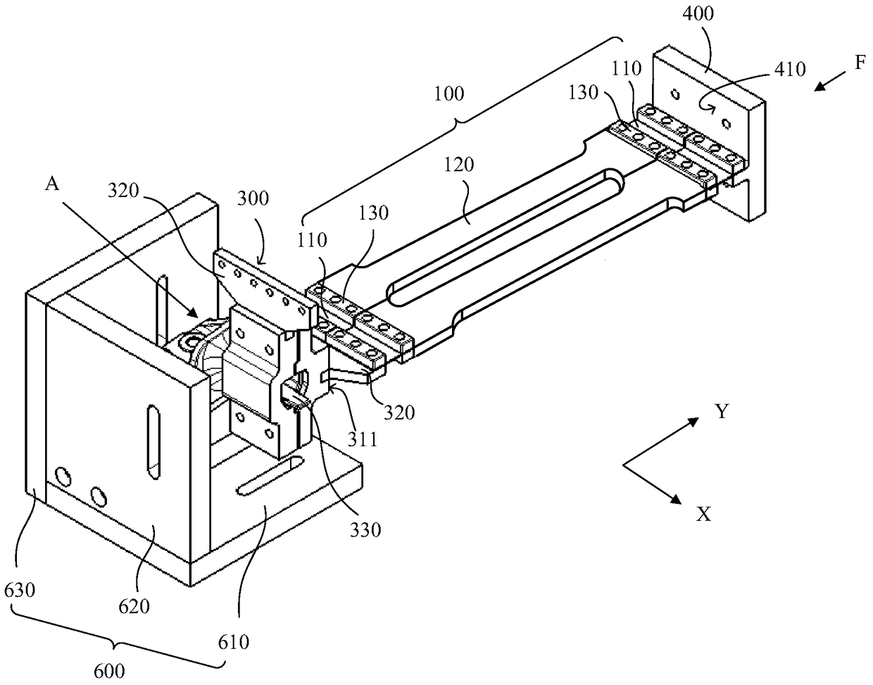
[0044] This embodiment provides a kind of fatigue test fixture, with reference to image 3 shown, including:

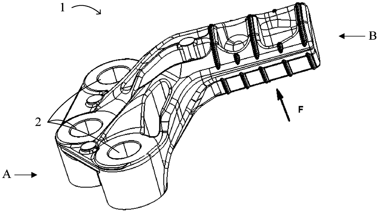
[0045] The clamping part 300 is formed with a clamping groove 330, and the clamping groove 330 has a side wall 340 extending along a first direction X, wherein the first direction X is perpendicular to the force direction F of the clamp during the test; the clamping part 300 For clamping the force-bearing end of the test part A, specifically, the force-bearing end of the test part A is clamped in the slot 330;

[0046] The coupling part 400 has a coupling surface 410; the coupling part 400 is used to connect a force applying device (not shown in the figure), such as a hydraulic servo actuator, etc., and the force applied by the force applying device is transmitted to the coupling surface 410 of the coupling part 400 , and then passed to the clamping part 300;

[0047] The first spring steel sheet group 100 is connected between the side wall 311 of the clamping part ...

no. 2 example

[0059] The difference between this embodiment and the above-mentioned embodiment is that, if Figure 5-6 As shown, the fatigue test fixture of this embodiment includes two first spring steel sheet groups 100, and also includes a second spring steel sheet group 200;

[0060] The second spring steel sheet group 200 includes two second spring steel sheets 210, and the second spring steel sheets 210 are perpendicular to the first spring steel sheets 110;

[0061] Two sets of first spring steel sheet groups 100 and the second spring steel sheet group 200 are connected in a staggered manner along the second direction Y, that is, the second spring steel sheet group 200 is connected to the above two groups of first spring sheets along the second direction Y. Between 100 steel sheet groups.

[0062] In this embodiment, each group of first spring steel sheets 100 includes a first spring steel sheet 110; the second spring steel sheet group 200 is a group, which includes two second sprin...


PUM


Abstract

A fatigue test clamp includes a clamping part provided with a card slot with a side wall extending along a first direction, a coupling part provided with a coupling surface, at least a first spring steel sheet group connected between the side wall of the card slot and the coupling surface of the coupling part and being parallel to a second direction, wherein the first direction is perpendicular to a stress direction of the clamp during testing, the second direction is parallel to the stress direction of the clamp during testing, and the first spring steel sheet group comprises at least one first spring steel sheet. By utilizing characteristics of the spring steel sheet that the spring steel sheet is high in rigidity at the plane direction and low in bending rigidity in a direction perpendicular to the plane direction, the clamp is good in flexibility, a bending moment generated due to over-constraint between the test clamp and a component in a testing process is avoided, the over-constraint between the test clamp and the component is decoupled properly, and accuracy of experiment data is improved.

Description

technical field [0001] The invention relates to the field of test fixtures, in particular to a fatigue test fixture for a suspension arm of an automobile power assembly. Background technique [0002] The powertrain suspension system of a car is one of the most important safety components of a car. Its main function is to connect the powertrain of the car including the engine and gearbox to the body or frame through the suspension arm (or bracket). [0003] Such as figure 1 Shown is a schematic diagram of the three-dimensional structure of an engine suspension arm. The base end A of the suspension arm 1 is connected to the powertrain of the vehicle through the bolt hole 2, and the arm end B opposite to the base end is connected to the body or frame. End B is coupled to the body or frame by a suspension of rubber material. In the actual stress situation, the suspension arm 1 bears the load generated by the driving torque of the engine along the forward or backward direction ...

Claims


Application Information

Patent Timeline
Patent Type & Authority Patents(China)
IPC IPC(8): G01N3/04
Inventor 孙明孙威韩愈琪
Owner SAIC MOTOR
Why Eureka
Try Eureka