Energy-storing type energy-saving alternating-current contactor

An AC contactor, energy storage technology, used in relays, electrical components, circuits, etc., can solve the problems that the control circuit cannot be energized for a long time, the use environment is limited, and it cannot be released.

Inactive Publication Date: 2012-12-26
FATO MECHANICAL & ELECTRICAL
View PDF3 Cites 9 Cited by
  • Summary
  • Abstract
  • Description
  • Claims
  • Application Information

AI Technical Summary

Problems solved by technology

Although the locking type (magnetic holding) and permanent magnet type have better energy-saving effects, there are still fatal shortcomings. They cannot be released when the power is off, and the control circuit cannot be energized for a long time, so the use environment is greatly restricted.
[0004] Because the principle of the contactor is that when the contactor coil is energized, the coil current will generate a magnetic field, and the generated magnetic field will cause the iron core to generate electromagnetic attraction to attract the moving iron core, and drive the contact action of the AC contactor, and the normally closed contact will be disconnected. , the normally open contact is closed, and the two are linked; when the coil is powered off, the electromagnetic attraction disappears, and the armature is released under the action of the release spring to restore the contact, the normally open contact is disconnected, and the normally closed contact is closed. However, there is a problem with energy-saving contactors in general, that is, after the iron core is magnetized, to maintain the magnetism of the iron core, it is necessary to continue to supply current, and the energy-saving effect will be weakened a lot, and the magnetic holding method is adopted, and power is required when the contact is released. , Once the power is cut off, it cannot be released, which will bring accident hazards to the operation of the contactor

Method used


Image

  • Energy-storing type energy-saving alternating-current contactor
  • Energy-storing type energy-saving alternating-current contactor

Examples


Embodiment Construction

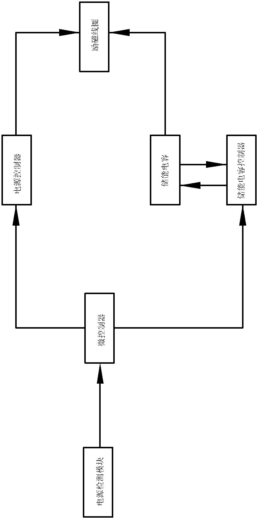
[0013] refer to figure 1 It can be seen that the output terminal of the power detection module is connected with the input terminal of the microcontroller, the output terminal of the microcontroller is connected with the power supply controller and the energy storage capacitor controller respectively, the output terminal of the power supply controller is connected with the excitation coil, and the energy storage capacitor The controller is connected to the energy storage capacitor, and the output terminal of the energy storage capacitor controller is connected to the exciting coil. After closing, the power supply is stopped, and the pull-in state is maintained by residual magnetism. When the power is cut off, the energy storage capacitor demagnetizes the excitation coil to achieve the purpose of release. During the whole process, only a little power is consumed, and the energy-saving effect is very obvious.

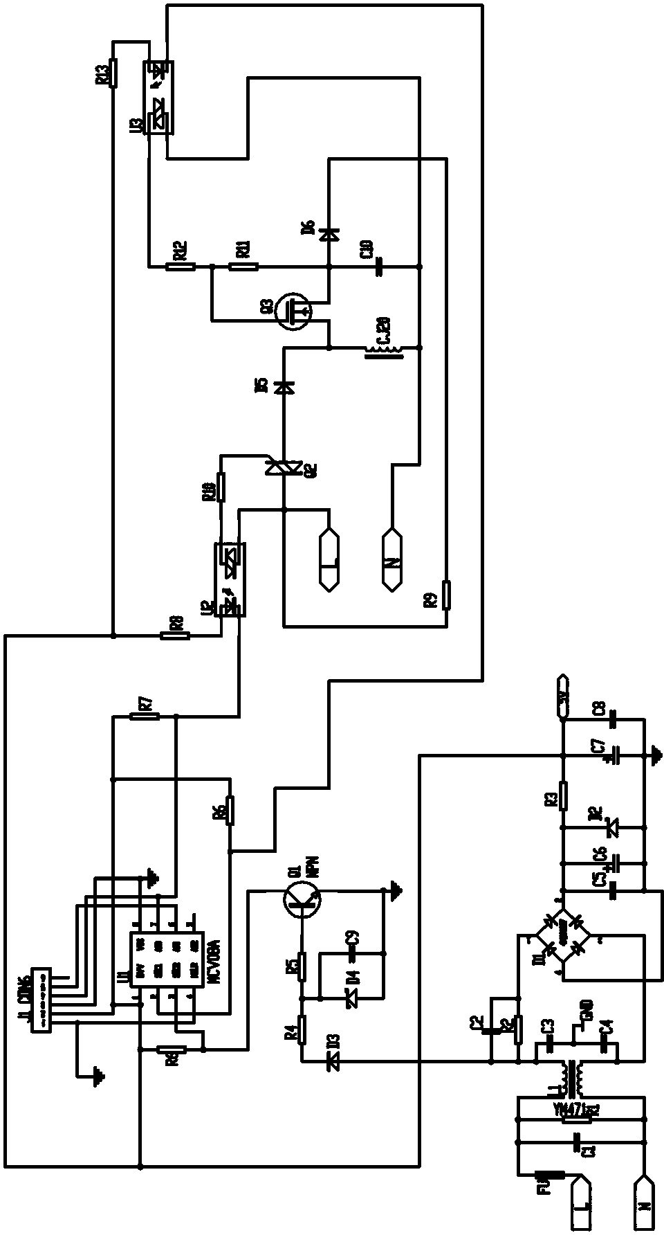
[0014] combine figure 2 It can be seen that the power input passes...


PUM


Abstract

The invention relates to a contactor, in particular to an energy-storing type energy-saving alternating-current contactor comprising an electromagnetic system. The electromagnetic system comprises an iron core and a coil. An output end of a power supply detecting module is connected with an input end of a microprocessor. An output end of the microprocessor is respectively connected with a power supply controller and an energy-storing capacity controller. An output end of the power supply controller is connected with a magnet exciting coil. The energy-storing capacity controller is connected with energy-storing capacity. An output end of the energy-storing capacity controller is connected with the magnet exciting coil. When power is on, the power supply controller controls charging and closing of the magnet exciting coil, the energy-storing capacity controller controls the energy-storing capacity to charge, supplying of the power is stopped after the magnet exciting coil is closed, and closing state is maintained through residual magnetism. When the power is off, the energy-storing capacity carries out demagnetizing treatment to the magnet exciting coil so that purpose of release is achieved. Energy-saving effects are obvious due to the fact that the whole process only consumes little energy.

Description

technical field [0001] The invention relates to a contactor, in particular to an energy storage energy-saving AC contactor. Background technique [0002] In a narrow sense, a contactor refers to a breaking and closing device that can frequently close, carry and break normal current and specified overload current. It applies to electricity, distribution and consumption. In a broad sense, a contactor refers to an electrical appliance that uses a coil to flow through a current to generate a magnetic field to close the contacts in order to control the load. The contactor is composed of an electromagnetic system (moving iron core, static iron core, electromagnetic coil) contact system ( Normally open contact and normally closed contact) and arc extinguishing device. [0003] At present, there are many energy-saving AC contactors on the market. Although the energy-saving effect reaches 90-95%, they still fall into the second-level energy consumption category of the national stan...

Claims


Application Information

Patent Timeline
IPC IPC(8): H01H47/02
Inventor 金则坚
Owner FATO MECHANICAL & ELECTRICAL
Why Eureka
Try Eureka