System and method for regulating inductive power transmission

A technology of inductive transmission and regulator, applied in transmission systems, near-field transmission systems, control/regulation systems, etc., and can solve problems such as jeopardizing the size of the system

Inactive Publication Date: 2012-12-26
POWERMAT TECHNOLOGIES
View PDF3 Cites 5 Cited by
  • Summary
  • Abstract
  • Description
  • Claims
  • Application Information

AI Technical Summary

Problems solved by technology

Significant design work is required to resolve this issue and can compromise other factors such as the size of the system

Method used


Image

  • System and method for regulating inductive power transmission
  • System and method for regulating inductive power transmission
  • System and method for regulating inductive power transmission

Examples


Embodiment Construction

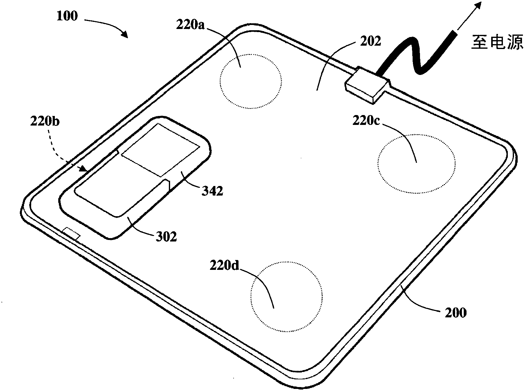
[0031] now refer to Figure 1a and 1b , Figure 1a and Figure 1b An inductive power transfer system 100 according to a first embodiment is shown. The transmission system 100 includes an inductive power outlet 200 and an inductive power receiver 300 . The inductive power outlet 200 is configured to wirelessly transfer electrical energy to the inductive power receiver 300 using electromagnetic induction.

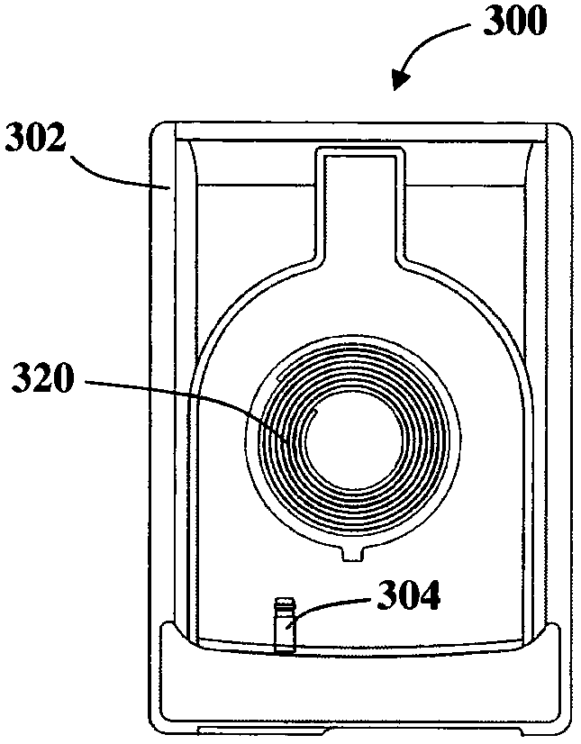
[0032] The inductive power outlet 200 of the first embodiment consists of four primary inductors 220a - d incorporated into the platform 202 . The inductive power receiver 300 includes a secondary inductor 320 incorporated into a housing for housing a mobile phone 342 . The power connector 304 electrically connects the secondary inductor 320 to the mobile phone 342 when the mobile phone 324 is placed into the housing 302 . Such as Figure 1a As shown, inductive power receiver 300 may be placed on platform 202 in alignment with primary inductor 220b such that secondary ind...


PUM


Abstract

An inductive power receiver is presented for providing a regulated power output to an electric load. The receiver inductively couples with an inductive power transmitter to form an inductive transfer system. A receiver-side regulator is provided to regulate the output voltage of the inductive transfer system. The regulator has a resonance-altering component and a switching unit configured to selectively connect the resonance-altering component to the reception circuit such that the amplitude of the induced voltage is controlled.

Description

technical field [0001] The invention relates to the regulation of electrical energy in contactless electrical transmission systems. More specifically, the present invention relates to receiver-side power conditioning for inductive power transfer systems. Background technique [0002] The inductive power transfer system is a convenient alternative to the common plug-and-socket power connection for providing power. Inductive power transfer allows power to be transferred from an inductive power outlet to an inductive power receiver without wiring. [0003] An oscillating electron potential or drive voltage is applied to the primary inductance associated with the inductive power outlet. This creates a changing magnetic field around the primary inductance. When the inductive receiver approaches the inductive outlet, a secondary potential difference or output voltage is generated across the secondary inductance within this changing inductive electric field. The output voltage ...

Claims


Application Information

Patent Timeline
Patent Type & Authority Applications(China)
IPC IPC(8): H02J5/00
CPCH02J5/005H02J50/402H02J50/12H02J7/04H04B5/0075H04B5/0037H03H3/0077G05F3/06
Inventor 阿勒克·罗费阿米尔·本-沙洛姆奥拉·格林沃尔德阿尔弗雷德·莱博维茨
Owner POWERMAT TECHNOLOGIES
Why Eureka
Try Eureka