Eureka AIR delivers breakthrough ideas for toughest innovation challenges, trusted by R&D personnel around the world.

Automatic film cutting device of film spreading machine

A technology of film laying machine and film device, which is applied in plant protection covers, metal processing, etc., can solve problems such as reduced operation quality, tooth removal, and excessive labor, and achieve stable and reliable performance, good film cutting effect, and high operation quality. Effect

Inactive Publication Date: 2015-06-03
SHAOWU BRANCH OF NANPING TOBACCO +1
View PDF7 Cites 0 Cited by
  • Summary
  • Abstract
  • Description
  • Claims
  • Application Information

AI Technical Summary

Problems solved by technology

[0004] 1. The position of the cutter is fixed by the pawl clamping the large pulley. When in use, the pawl needs to be moved away frequently, and then the film is cut due to gravity and the gravity of the film cutter. The force of the entire film cutting is not strong enough to fully Remove the film on the entire ridge
[0005] 2. The pawl needs to cooperate with the large pulley continuously during use. After a long time of use, it is prone to tooth loss, causing the film cutter to fall when needed, causing damage to the entire crop.
[0006] 3. When the pawl is released, the film is mainly cut off by the restoring force of the spring. The whole spring needs to be in a compressed state all the time. The elastic deformation of the spring can easily become plastic deformation, which leads to the decline of the film cutting force and improves the working quality. Reduced, the overall work is not stable enough
[0007] 4. After cutting the film, it is necessary to manually turn the handle to reverse the large pulley to lift the entire film cutting knife, and then use the pawl to block the large pulley. The whole process is complicated and requires a lot of labor

Method used


Image

  • Automatic film cutting device of film spreading machine
  • Automatic film cutting device of film spreading machine
  • Automatic film cutting device of film spreading machine

Examples


Embodiment Construction

[0027] In order to describe the technical content, structural features, achieved goals and effects of the present invention in detail, the following will be described in detail in conjunction with the embodiments and accompanying drawings.

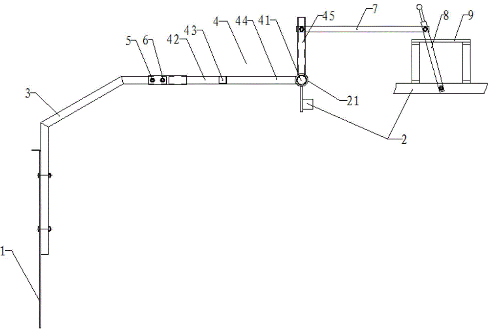
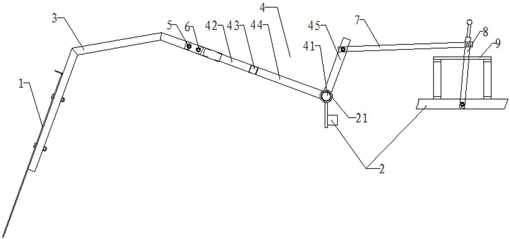
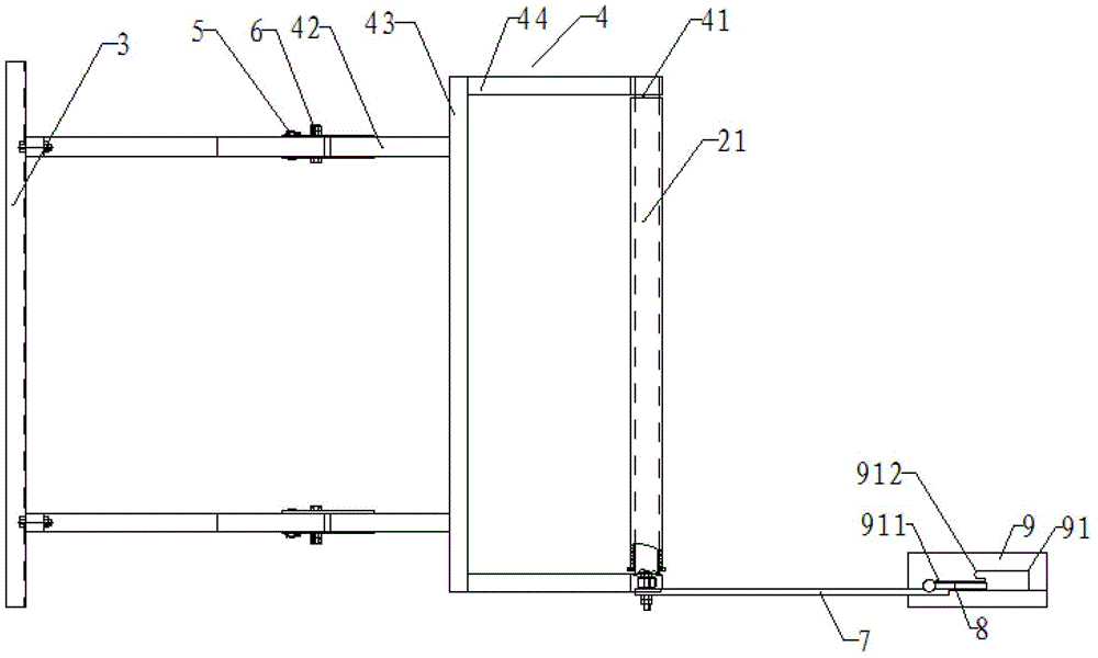
[0028] Please refer to the attached figure 1 to attach Figure 6 , as shown in the accompanying drawings, an automatic film cutting device of a film laying machine provided by the present invention includes:

[0029] cutter 1;

[0030] Cutter holder, the cutter 1 is fixed on the cutter holder;

[0031] The driving device, the cutter fixing frame is driven by the driving device to be swingably arranged on the frame 2 of the film laying machine, and the cutter fixing frame drives the cutter 1 to cut off the film covered on the furrow 10 while swinging.

[0032] When running, first start the driving device, the driving device drives the cutter fixed frame to swing on the frame 2 of the film laying machine, and further drives the movement o...


PUM


Abstract

The invention discloses an automatic film cutting device of a film spreading machine. The automatic film cutting device comprises a cutting knife, a cutting knife fixing frame where the cutting knife is fixed, and a drive device, wherein the cutting knife fixing frame is driven by the drive device and can be arranged on a machine frame of the film spreading machine in a swing way; and the cutting knife is driven to cut off a film covering a ridge while the cutting knife fixing frame swings. A novel automatic film cutting structure is used with the whole film spreading machine in a matched way, the whole cutting knife fixing frame can be driven to swing through a simple operation of the drive device so as to further drive the cutting knife to move for cutting off the film covering the ridge, and the whole cutting knife is in rigid connection with the drive device, so that the automatic film cutting device has a good film cutting effect, and is high in operating quality, stable and reliable in performance and simple in structure.

Description

technical field [0001] The invention relates to the field of agricultural machinery, in particular to an automatic film cutting device for a film laying machine. Background technique [0002] With the continuous development of agricultural machinery, agricultural machinery products continue to be used in actual production. In recent years, the application of film laying machines in the field of crop planting and regional application has gradually expanded, especially in tobacco planting in the southern region. Traditional manual film covering is gradually being used. However, the existing film laying machine can only cover the film, and when it reaches the field, people have to manually cut off the film, which is labor-intensive, labor-intensive, and low-efficiency. [0003] The patent publication number is "CN100479648C", and the name is "automatic film cutting device for mulching machine". It discloses an automatic film cutting device for mulching machine, including a film...

Claims


Application Information

Patent Timeline
Patent Type & Authority Patents(China)
IPC IPC(8): A01G13/02B26D1/01
Inventor 曾桂溪
Owner SHAOWU BRANCH OF NANPING TOBACCO
Why Eureka
Eureka Blog
Learn More