Eureka AIR delivers breakthrough ideas for toughest innovation challenges, trusted by R&D personnel around the world.

Rotary electromagnetic actuating mechanism and car lamp upper and lower beam switching device thereof

A technology of executive mechanism and switching device, which is applied in the direction of headlights, signal devices, vehicle components, etc., can solve the problem of high noise of the high and low light switching mechanism, achieve large shading plate adjustment stroke, reduce restrictions, improve service life and reliability sexual effect

Active Publication Date: 2013-01-02
HASCO VISION TECHNOLOGY CO LTD
View PDF9 Cites 26 Cited by
  • Summary
  • Abstract
  • Description
  • Claims
  • Application Information

AI Technical Summary

Problems solved by technology

[0006] The purpose of the present invention is to provide a rotary electromagnetic actuator used for the high and low beam switching device of the car lamp. By changing the movement form of the electromagnetic actuator, the technical problem of the high noise of the high and low beam switching mechanism is solved when it is working.

Method used


Image

  • Rotary electromagnetic actuating mechanism and car lamp upper and lower beam switching device thereof
  • Rotary electromagnetic actuating mechanism and car lamp upper and lower beam switching device thereof
  • Rotary electromagnetic actuating mechanism and car lamp upper and lower beam switching device thereof

Examples


Embodiment Construction

[0033] In order to better understand the above technical solutions of the present invention, a further detailed description will be given below in conjunction with the drawings and embodiments.

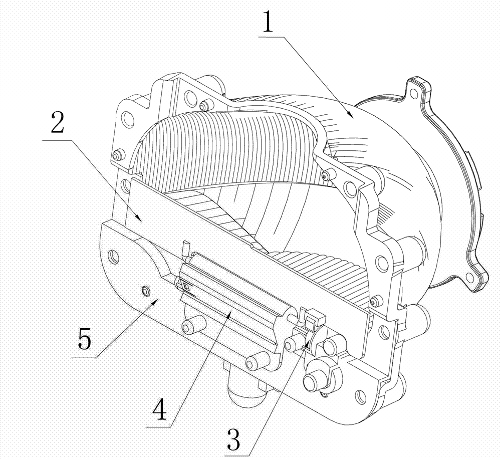
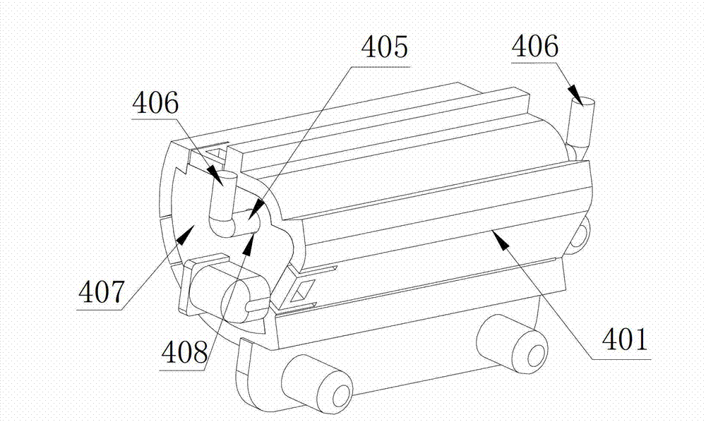
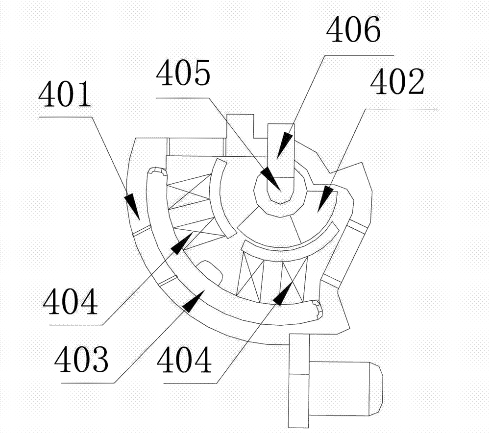
[0034] An example of the rotary electromagnetic actuator of the present invention is figure 2 and image 3 as shown, Figure 4 It is a schematic diagram of the structure of the rotary electromagnetic actuator with a visor rotating to the action position. In the embodiment of the rotary electromagnetic actuator shown in the drawings, it includes a housing 401, a rotor 402, a stator 403, a rotating shaft 405 and an end cover 407, which are used to drive the visor 2 of the high and low beam switching device of the vehicle lamp. In order to more clearly show the internal structure of the rotary electromagnetic actuator 4 of the present invention, image 3 and Figure 4 The end cap 407 is omitted.

[0035] The stator 403 is provided with a stator winding 404, and the stator 403 and t...


PUM


Abstract

The invention discloses a rotary electromagnetic actuating mechanism and a car lamp upper and lower beam switching device thereof, and relates to an illuminating device or functional characteristics or parts of a system of the illuminating device. The rotary electromagnetic actuating mechanism comprises a shell, a rotor, a stator, a rotary shaft and an end cover; stator windings are arranged on the stator, and the stator and the stator windings are fixedly mounted in the shell to form a pair of arc-shaped stator magnetic poles capable of being electrified to be excited; the rotor is an arc-shaped permanent magnet, is fixed onto the rotary shaft, is placed in magnetic field space of the arc-shaped stator magnetic poles and is matched with the arc-shaped stator magnetic poles, so that a closed magnetic circuit with air gaps is formed; and two ends of the rotary shaft are respectively connected with two oscillating bars radially extending along the rotary shaft. A shading plate of the car lamp upper and lower beam switching device is fixedly connected onto the oscillating bars at the two ends of the rotary shaft, an oscillating angle of the shading plate is identical to a rotation angle of the rotor, the rotary electromagnetic actuating mechanism drives the shading plate to realize switching between upper beams and lower beams, collision noise generated when electromagnets are sucked and released is avoided, and a comfortable driving environment is provided for users.

Description

technical field [0001] The present invention relates to a lighting device or the functional features or parts of its system, in particular to a rotary electromagnetic actuator that changes the characteristics and distribution of light emission by means of adjusting parts, and a high and low beam switching device for a car lamp. Background technique [0002] When the driver is driving, it is inevitable that there will be car meeting and uphill and downhill situations. Especially when the car is driving at night, the lights of the opposite cars and the reflected light of the road when going up and down will affect the driver's vision. If it is too strong, the driver will not be able to see the road ahead, so the driver needs to switch in time. If the far and near beams of the car are not switched in time, it may cause traffic accidents. Therefore, modern vehicles widely use far and near beam switching mechanisms to realize the far and near beam switching control of automobile...

Claims


Application Information

Patent Timeline
Patent Type & Authority Applications(China)
IPC IPC(8): B60Q1/14
CPCF21S41/689
Inventor 于世杰朱明华郭田忠
Owner HASCO VISION TECHNOLOGY CO LTD
Why Eureka
Eureka Blog
Learn More