
Engine rotational speed display device

A technology of engine speed and display device, which is applied in the direction of engine control, machine/engine, measuring device, etc., which can solve the problems of driver's discomfort, sudden change of engine speed cannot fully respond, engine speed cannot be changed immediately, etc.

Inactive Publication Date: 2013-01-02
HONDA MOTOR CO LTD
View PDF6 Cites 14 Cited by
  • Summary
  • Abstract
  • Description
  • Claims
  • Application Information

AI Technical Summary

Problems solved by technology

[0005] According to the above-mentioned engine speed display device, although it is effective in determining a stable engine speed, when the speed changes rapidly, for example, the display immediately after the engine stops or the engine is stopped due to improper start operation of the MT car, etc. , There is a delay in the display of the engine speed. Although the engine is stopped, the engine speed cannot be immediately changed to "0" in the display, which will give the driver an uncomfortable feeling. It cannot fully respond to rapid changes in the engine speed.

Method used


Image

  • Engine rotational speed display device
  • Engine rotational speed display device
  • Engine rotational speed display device

Examples


Embodiment Construction

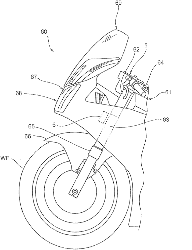
[0036] An example of an embodiment of the engine speed display device according to the present invention will be described with reference to the drawings. figure 1 It is a side view showing the front portion of a motorcycle provided with an engine speed display device according to an embodiment of the present invention.

[0037] The two-wheeled vehicle 60 includes a body frame 61 , and a head pipe 63 , which pivotally supports a steering rod 62 , is coupled to a front end portion of the body frame 61 . A pair of left and right steering handlebars 64 are attached to the upper portion of the steering rod 62 . At the center of the steering handlebar 64 is disposed an instrument section 5 , and the instrument section 5 is provided with a speedometer (speedometer), a tachometer (engine tachometer), a fuel gauge, a distance gauge, various indicator lights, and the like. Attached to a lower portion of the steering rod 62 are a pair of left and right front forks 65 (only one side is ...


PUM


Abstract

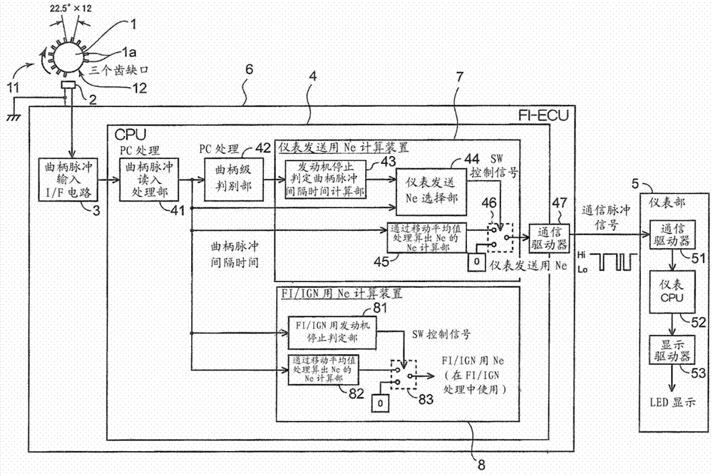
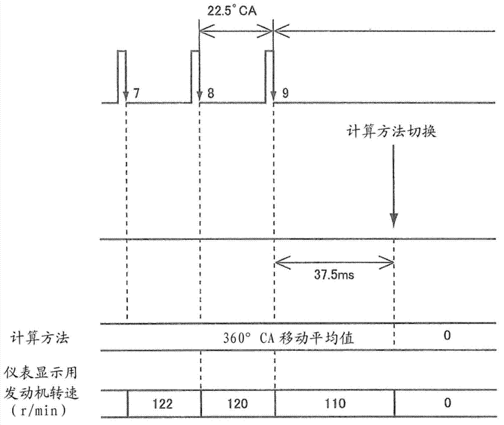
To enable an engine rotational speed display device to display an engine rotational speed without causing a sense of incongruity by following changes in the engine rotational speed at times of sharp variations. An engine rotational speed display device includes: a rotational speed sensor (2) for detecting a crankshaft rotational speed pulse according to rotation of a crank pulse rotor (1) provided to a crankshaft of an engine; an engine rotational speed calculating means (7) for calculating an engine rotational speed by a moving average of a detected value of the crankshaft rotational speed pulse; and a display means (5) for displaying the engine rotational speed on a meter by electrical processing. When the crankshaft rotational speed pulse is not detected in a detection time equal to or more than a predetermined value, the engine rotational speed calculating means (7) determines that the engine rotational speed is "0" without calculating the engine rotational speed by the moving average, and the engine rotational speed of "0" is displayed on the meter.

Description

technical field [0001] The present invention relates to a device for displaying the engine speed on a tachometer mounted on a two-wheeled motor vehicle, and more particularly to an engine speed display device capable of displaying the engine speed electrically even when the engine speed fluctuates rapidly. Can be expressed in a way that does not cause discomfort. Background technique [0002] Conventionally, when the engine speed display device electrically displays the engine speed, the crankshaft speed pulse is detected by the speed sensor, and the engine speed is calculated by using the moving average of the detection value of the crankshaft speed pulse. The crank pulse of the crankshaft is generated by the rotation of the rotor. [0003] In the above-mentioned engine speed display device, when the engine speed is in a low speed range, a change in the accuracy of the speed sensor affects the speed display, thereby deteriorating the visibility of the speed display. There...

Claims


Application Information

Patent Timeline
Patent Type & Authority Applications(China)
IPC IPC(8): G01P3/481F02D45/00
CPCB60K35/00B60Y2200/12B62J50/22B60W2510/0638B60K35/10B60K35/28B60K35/50B60K35/22B60K35/60
Inventor 中村公纪町田健一
Owner HONDA MOTOR CO LTD
Learn More