Temporary roof cover of nuclear island safety shell

A containment and temporary technology, which is applied in the field of temporary roof, can solve the problems of failure to meet the construction progress and safety requirements of the third-generation nuclear power project, labor and time-consuming installation and disassembly, and equipment cannot be protected, etc., to achieve simplified transmission and layout, Reduced man-hours, flexible opening and closing operations

Active Publication Date: 2015-03-11
SHANGHAI NUCLEAR ENG RES & DESIGN INST CO LTD
View PDF5 Cites 0 Cited by
  • Summary
  • Abstract
  • Description
  • Claims
  • Application Information

AI Technical Summary

Problems solved by technology

However, there are some problems in the current design of the temporary roof, which cannot meet the construction progress and safety requirements of the third-generation nuclear power project while playing the role of the temporary roof
At present, the temporary roof used in construction requires personnel to stand on the roof and use manual methods to gather or open the waterproof material. The main disadvantage is that the installation and disassembly are labor-intensive and time-consuming, and working at heights also increases the risk of construction. factor; frequent installation and dismantling of joints will reduce the waterproof performance, which may easily cause leakage; the original temporary roof can only be installed on the ring plate of the containment with ring hanging beams, and cannot be installed on other lower ones without ring hanging beams ring plate, resulting in the inability to protect the relevant equipment inside the containment at this time

Method used


Image

  • Temporary roof cover of nuclear island safety shell
  • Temporary roof cover of nuclear island safety shell
  • Temporary roof cover of nuclear island safety shell

Examples


Embodiment Construction

[0018] In order to make the present invention more comprehensible, preferred embodiments are described in detail below with accompanying drawings.

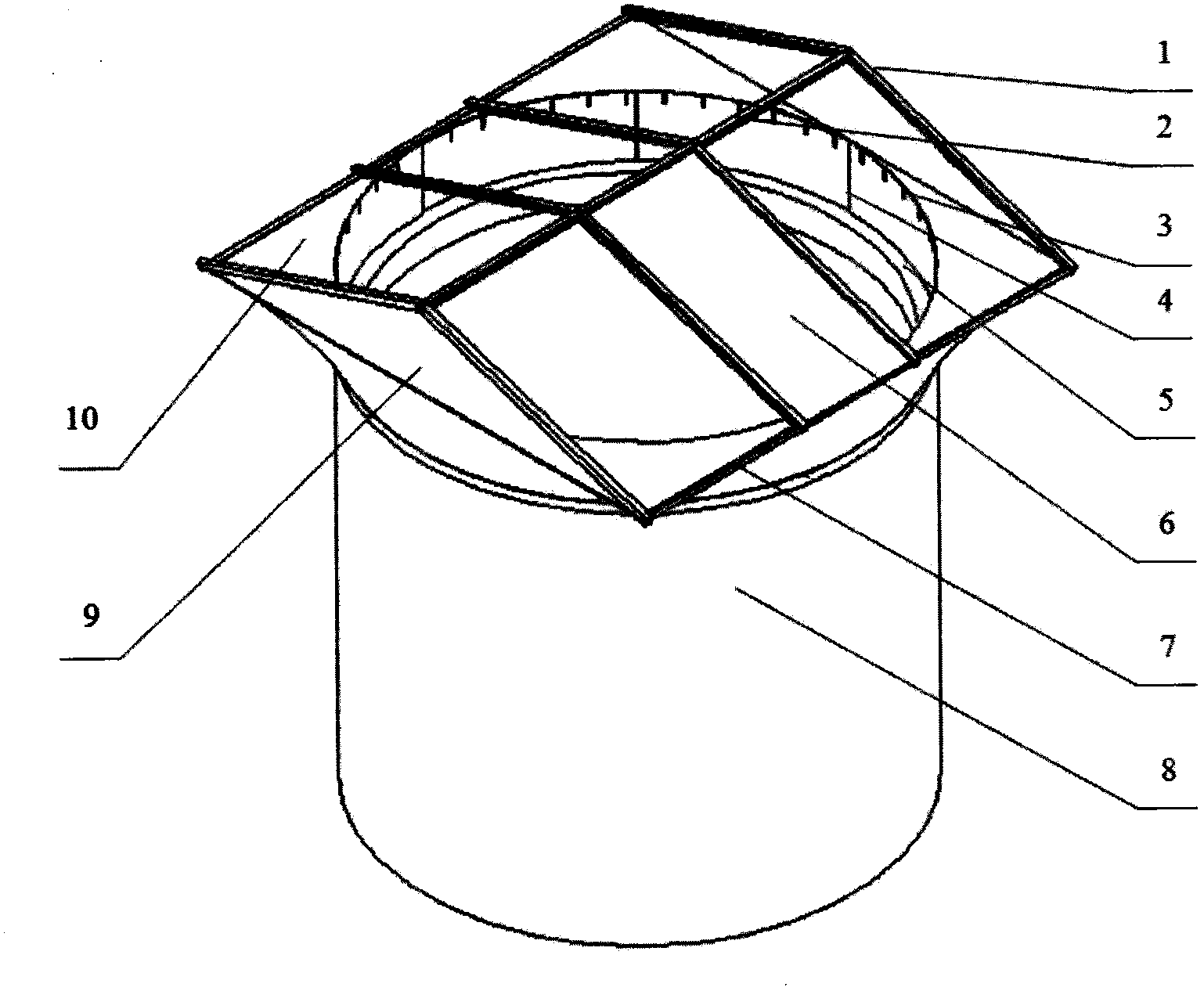
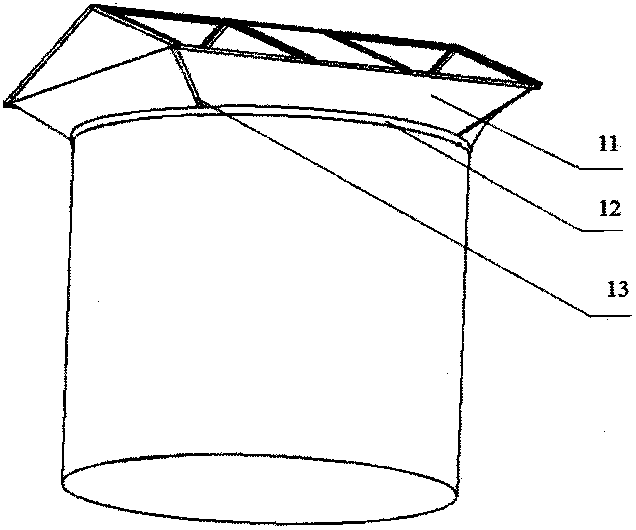
[0019] Such as figure 1 and figure 2 As shown, the temporary roof of the nuclear island containment vessel disclosed in this embodiment includes a roof-shaped three-dimensional frame on the top, and the three-dimensional frame is the top cover of the temporary roof of the entire nuclear island containment vessel. The section of the space frame is triangular. The space frame comprises beams 2 at the top. The crossbeam 2 can be designed as three independent sections, and a certain section can be temporarily disassembled when hoisting super-large and super-long pieces. The first waterproof material 9 is respectively fixedly installed on the left and right sides of the beam 2 in a direction perpendicular to the cross-section of the three-dimensional frame. Four oblique and detachable slanting beams 1 are connected to the front an...


PUM


Abstract

The invention relates to a temporary roof cover of a nuclear island safety shell. The temporary roof cover of the nuclear island safety shell is characterized by comprising a vertical frame at the top part; the section of the vertical frame is triangular; movable waterproof materials capable of being remotely controlled to open or roll through a remote control drive mechanism are covered on an inclined plane from the peak of the vertical frame to the upper parts of two sides; the vertical frame is provided with a square base; the base completely covers an annular plate of the safety shell; the base and the annular plate of the safety shell are in transition through a transition stricture; the transition stricture is provided with a square opening matched with the base and a round opening matched with the top end of the annular plate of the safety shell. According to the temporary roof cover, a fixed thinking mode that a traditional round truss top cover is connected with the cylindrical safety shell is broken through; the structure of the temporary roof cover is planarized; transmission and arrangement are simplified, so that the waterproof material is more flexible to open and close; a plurality of waterproof materials are independently driven; the construction efficiency is improved; the manpower hour is shortened; the operating personnel is greatly facilitated; the personnel security is guaranteed, and a construction environment is improved.

Description

technical field [0001] The invention relates to a temporary top cover of a nuclear island safety shell of a nuclear power plant, which is suitable for nuclear power plants that require construction by an open top method, and is also suitable for similar working conditions and environments of cylindrical or other shaped objects. Background technique [0002] The construction concept of the open roof method has changed the traditional boundary between construction and safety, and has become one of the more commonly used methods for the construction of third-generation nuclear power projects. However, the construction method using the open roof method is likely to cause rainwater to enter the containment during the construction process, which brings inconvenience to the construction and causes damage to building materials and special equipment. The installation of the temporary roof of the nuclear island containment is a temporary measure for the open top method, which can solv...

Claims


Application Information

Patent Timeline
Patent Type & Authority Patents(China)
IPC IPC(8): G21C13/02
CPCY02E30/40Y02E30/30
Inventor 赵铁沈文荣
Owner SHANGHAI NUCLEAR ENG RES & DESIGN INST CO LTD
Why Eureka
Try Eureka