Movable door mechanism of high voltage switch cabinet

A technology of high-voltage switchgear and valves, which is applied in the direction of pull-out switchgear, switchgear, switchgear components, etc., can solve the problems of increased cabinet space, unreliable operation, loose cabinet structure, etc., and achieve greater safety High performance, flexible operation, and simplified mechanism

Active Publication Date: 2013-01-02
JIANGSU NARI POWER ELECTRIC
View PDF5 Cites 6 Cited by
  • Summary
  • Abstract
  • Description
  • Claims
  • Application Information

AI Technical Summary

Problems solved by technology

Since the main components of the cabinet are vertically arranged, in order to avoid the valve and other components, especially the busbar, causing failures caused by mutual interference, generally only increase the cabinet space, the valve transmission mechanism is often jammed, and the left and right movements are inconsistent, causing the valve to tilt, so Causes a series of problems such as unsafe maintenance switchgear, loose cabinet structure, unreliable operation, etc.

Method used


Image

  • Movable door mechanism of high voltage switch cabinet
  • Movable door mechanism of high voltage switch cabinet

Examples


Embodiment Construction

[0014] The present invention will be further described below in conjunction with the accompanying drawings.

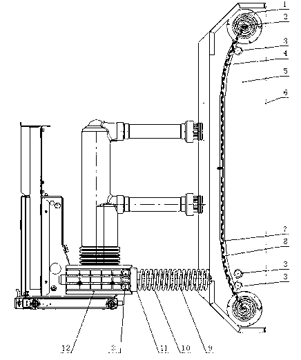
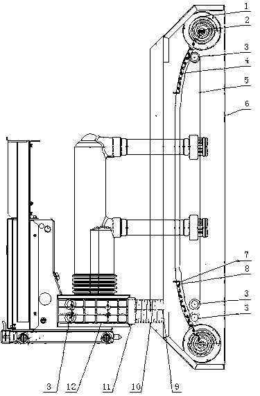
[0015] Such as figure 1 and figure 2 Shown is a valve mechanism for a high-voltage switchgear, including the valve, which is a rolling door that moves up and down, including an upper rolling door panel 4 and a lower rolling door panel 7; Guide rail; the guide rail is in the shape of a slightly convex curve toward the door; it also includes a transmission mechanism for driving the shutter door switch; the transmission mechanism includes soft steel wires 5, 8, fixed pulley 3 and slider 11; soft steel wires 5, 8 One end of the roller shutter door is fixedly connected to the end of the middle position of the rolling shutter door, and then arranged along the guide rail to lead out from the end of the guide rail respectively, bypassing a plurality of fixed pulleys 3 and the other end is fixedly connected to the slider 11; the slider 11 is sleeved on the guide rod 9 On; th...


PUM


Abstract

The invention discloses a movable door mechanism of a high voltage switch cabinet, the movable door mechanism comprises a movable door and is characterized in that the movable door is a roller shutter door capable of being movably and oppositely opened up and down, and the roller shutter door comprises an upper roller shutter door panel and a lower roller shutter door panel; guide rails used for guaranteeing the synchronous movement and accuracy of the two sides are installed on the two sides of the roller shutter door; the guide rails have curve shapes slightly protruding outwards; the movable door mechanism further comprises a driving mechanism used for driving the roller shutter door to open and close; the driving mechanism comprises a soft steel wire, dead pulleys and a slide block; one end of the soft steel wire is fixedly connected with the end part of the middle position of the roller shutter door and is respectively led out from the end parts of the guide rails along the guide rails, and the soft steel wire is fixedly connected with the slide block after rounding the other ends of a plurality of dead pulleys. The movable door mechanism of high voltage switch cabinet provided by the invention is safe and reliable, flexible in operation and convenient in use.

Description

technical field [0001] The invention relates to a valve mechanism of a high-voltage switch cabinet. Background technique [0002] At present, the requirements for the technical performance, operation and use, maintenance and other aspects of the removable high-voltage switchgear in the power system are getting higher and higher, especially the requirements for safety. As the cover of the charged body of the high-voltage switchgear, the accuracy and reliability of the opening and closing of the valve are particularly important. [0003] In high-voltage switchgear, in order to prevent the contacts from being electrified during maintenance and endanger the personal safety of the maintenance personnel, a valve mechanism is generally installed in the switch cabinet. When the handcart is pushed into the switch cabinet to work, the valve is opened; when the handcart is pulled out for maintenance, the valve is closed. , shield live contacts, thereby protecting the personal safety o...

Claims


Application Information

Patent Timeline
Patent Type & Authority Applications(China)
IPC IPC(8): H02B11/167H02B11/02
Inventor 刘骥张永刚孟斌阙连元徐萌
Owner JIANGSU NARI POWER ELECTRIC
Why Eureka
Try Eureka