Critical temperature testing system of gunpowder and explosive thermal explosion

A technology of critical temperature and test system, applied in the direction of material thermal development, etc., can solve problems such as personal safety threats, difficult data collection, failure to meet temperature field uniformity and stability requirements, etc., to improve temperature field uniformity and stability , the effect of ensuring personal safety

Inactive Publication Date: 2012-07-25
XIAN MODERN CHEM RES INST
View PDF4 Cites 27 Cited by
  • Summary
  • Abstract
  • Description
  • Claims
  • Application Information

AI Technical Summary

Problems solved by technology

[0004] (1) Under isothermal or temperature-programmed conditions, there is a certain ambient temperature before the powder column burns or explodes. For propellant and explosives with small size or low energy, samples with small heat release or samples with high thermal explosion critical temperature, The heat generated by decomposition, combustion, and explosion is not enough to cause a significant change in the ambient temperature, that is, when there is temperature interference, the traditional thermocouple temperature sensor judges the data of the characteristic response signal is not easy to collect, and the critical temperature of thermal explosion cannot be obtained
[0005] (2) At present, the temperature control accuracy of the domestic constant temperature explosion furnace tester is ±5°C, and the temperature measurement range is 0-200°C. Field uniformity, stability requirements, temperature field fluctuations affect the accuracy of thermal explosion critical parameters
[0006] (3) Manual sampling, personal safety is threatened when conducting large-scale sample experiments at high temperatures

Method used


Image

  • Critical temperature testing system of gunpowder and explosive thermal explosion
  • Critical temperature testing system of gunpowder and explosive thermal explosion
  • Critical temperature testing system of gunpowder and explosive thermal explosion

Examples


Embodiment Construction

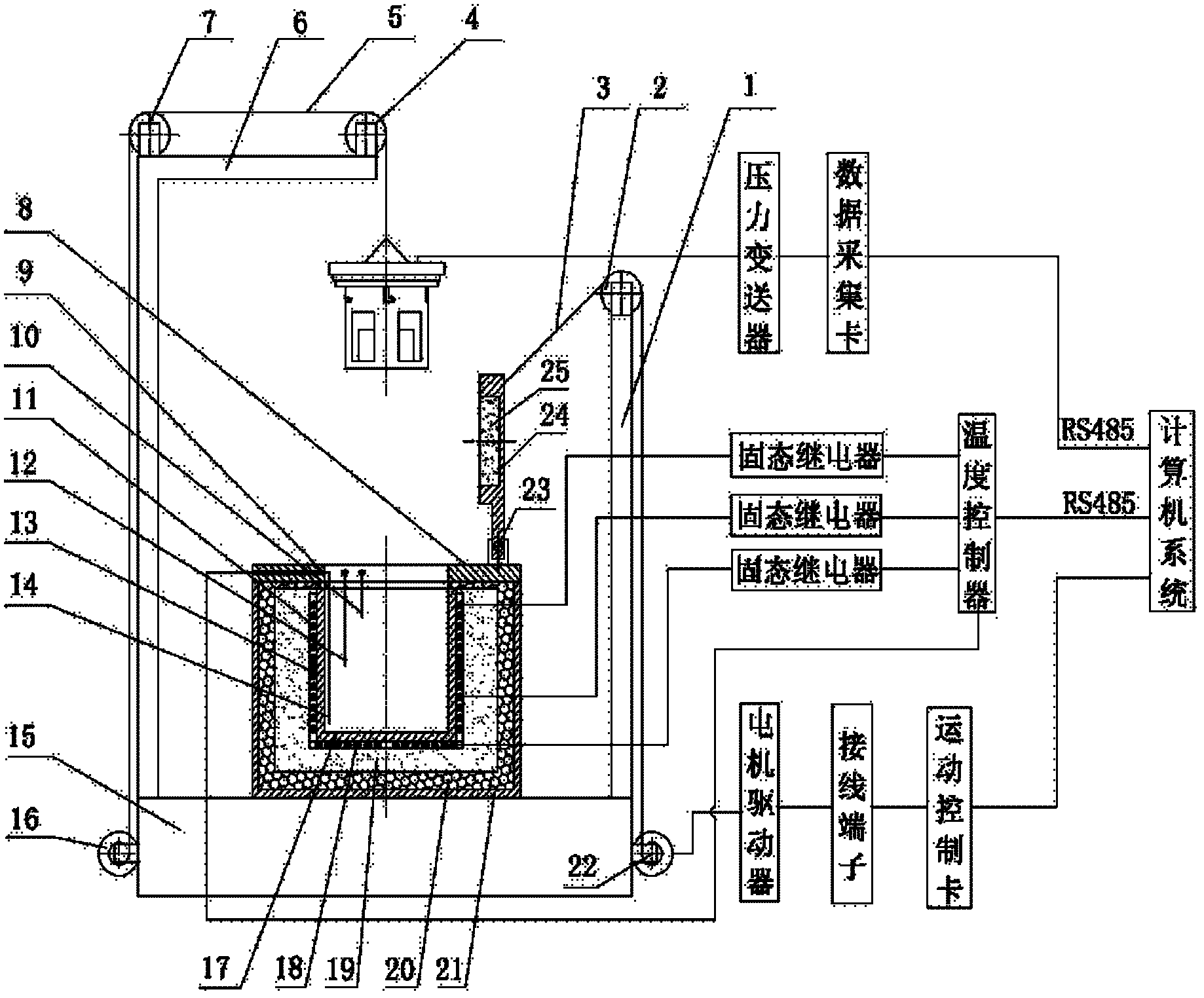
[0027] see Figure 1 ~ Figure 4 , the propellant thermal explosion critical temperature test system of the present invention includes a heating unit for heating, a reactor unit, an automatic sampling unit, a pressure detection unit and a computer.

[0028] The heating unit for heating comprises a single-cavity heating furnace body with a thermal conduction layer 17, three groups of heating layers (upper heating layer 11, middle heating layer 13, lower heating layer 18), asbestos insulation layer 19, and ceramic insulation layer 20. There are independent heating wires in the heating layer; the bottom, middle and upper parts of the furnace cavity are respectively equipped with an upper layer temperature sensor 10 connected to the computer, a middle layer temperature sensor 12, and a lower layer temperature sensor 14. There are solid state relays and temperature controllers outside the heating furnace body , the outermost layer of the heating furnace body is a shell 21, which is ...


PUM


Abstract

The invention discloses a critical temperature testing system of gunpowder and explosive thermal explosion, comprising a temperature-rising heating unit, a reactor unit, an automatic sample feeding unit, a pressure detection unit and a computer, wherein the temperature-rising heating unit comprises a heat-conducting layer, a heat preservation layer, and a single-cavity heating furnace body containing three groups of heating layers and ceramic heat-isolating layers; and the temperature and the temperature-rising speed of the heating furnace body are controlled by the computer. The reactor unit comprises a testing furnace cover, a lifting basket, a sample tank and a pre-heating furnace cover; the automatic sample feeding unit comprises a furnace body bracket, two stepping motors, a pulley wheel and a steel wire rope; the air pressure detection unit comprises a pressure sensor; the pressure sensor is mounted in the sample tank through the testing furnace cover and is connected with the computer; and the computer is provided with a data acquisition card, an image display control piece and a data processing unit. When the critical temperature testing system is used, a gunpowder or explosive sample with the certain size is placed into a special explosion-proof furnace and the sample is heated at the equal temperature or temperature-rising condition, so as to detect the thermal explosion critical temperature when the sample is combusted or exploded.

Description

technical field [0001] The invention belongs to the field of propellant and explosive performance testing, and mainly relates to a thermal explosion critical parameter testing device of propellant and explosive, in particular to a thermal explosion critical temperature test system of propellant and explosive. Place the sample in a special explosion-proof furnace, heat the sample under isothermal and non-isothermal conditions, and measure the thermal explosion critical temperature when the sample burns or explodes. Background technique [0002] In theory, explosives can be thermally decomposed at any temperature to release heat. Explosives will be subjected to temperature load and pressure load during the production process or long-term storage process. For the case of small powder column size or small accumulation size, the heat generated by the temperature load and pressure load can be dissipated in time, so There will be no self-heating and combustion. For the large-sized...

Claims


Application Information

Patent Timeline
Patent Type & Authority Applications(China)
IPC IPC(8): G01N25/26
Inventor 丁黎张腊莹王江宁刘文亮王琼康冰岳璞张超
Owner XIAN MODERN CHEM RES INST
Why Eureka
Try Eureka