Rotary compressor
A compressor and rotary technology, applied to compressors, rotary piston machines, irreversible cycle compressors, etc., can solve problems such as excess rise and loss, and achieve reduced pressure loss, high reliability, and suppressed reliability. Effect
- Summary
- Abstract
- Description
- Claims
- Application Information
AI Technical Summary
Problems solved by technology
Method used
Image

Examples
Embodiment approach 1)
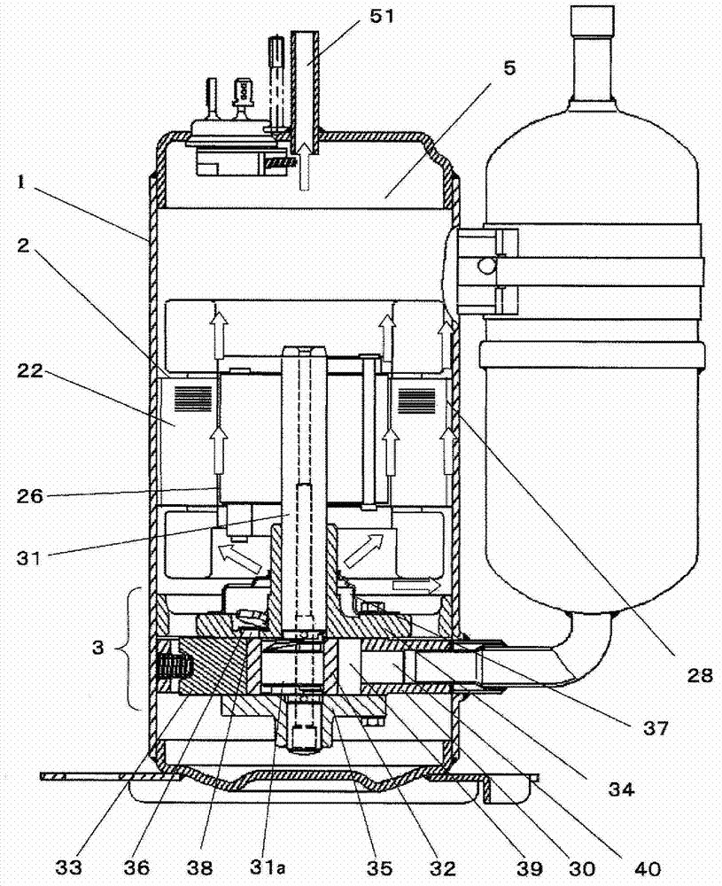
[0049] figure 1 It is a longitudinal sectional view of the hermetic compressor of Embodiment 1.
[0050] exist figure 1 Among them, the rotary compressor connects the motor 2 and the compression mechanism part 3 with a crankshaft 31 and accommodates it in the airtight container 1. The compression mechanism part 3 includes: a cylinder 30; A compression chamber 39 formed by 35; a roller 32 fitted with the eccentric portion 31a of the crankshaft 31 supported by an upper end plate 34 and a lower end plate 35 in the compression chamber 39; The vane 33 rotates and reciprocates to partition the inside of the compression chamber 39 into a low-pressure part and a high-pressure part.
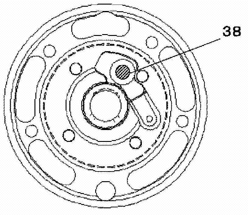
[0051] A suction port 40 for sucking gas into the low-pressure part in the compression chamber 39 is opened in the cylinder 30, and a discharge port 38 for discharging gas from the high-pressure part converted from the low-pressure part in the compression chamber 39 is opened in the upper end plate 34...
Embodiment approach 2)
[0074] Figure 5 It is a sectional view of the compression mechanism part 3 of Embodiment 2. This second embodiment differs from the first embodiment in the points described below, but is basically the same as the first embodiment in other points, so repeated explanations are omitted, and only the different parts will be described. The same applies to each embodiment described below.
[0075] Such as Figure 5 As shown, the upper and lower end plates 34 and 35 are respectively provided with a discharge port 38 and a lower discharge port 35a. The positions of the discharge port 38 and the lower discharge port 35a are vertically symmetrical. That is, it is provided at a position where the rotation angle of the crankshaft 31 is the same when the compression chamber 39 communicates with the discharge port 38 and the lower discharge port 35a. In addition, the area obtained by adding the opening areas of the discharge port 38 and the lower discharge port 35a respectively provide...
Embodiment approach 3)
[0079] Figure 6 It is an enlarged view of the periphery of the discharge port 38 in the third embodiment. Such as Figure 6 As shown, a convex portion 38 a corresponding to the discharge valve 36 is provided on the opposite side of the compression chamber 39 of the upper end plate 34 . Therefore, the discharge valve 36 is in line contact with the convex portion 38a. Due to the line contact, the pressure from the discharge valve 36 to the convex portion 38a is increased, and the sealing performance is improved, so leakage from the discharge valve 36 can be prevented, re-expansion can be suppressed, and a rise in discharge temperature can be suppressed, so the decomposition of the refrigerant can be suppressed.
[0080] In addition, the discharge valve 36 is provided with a protrusion 36a, and when the discharge valve 36 is closed, the protrusion 36a is inserted into the discharge port 38, so that the dead volume of the compression chamber 39 can be reduced, and overcompressi...
PUM
 Abstract
Description
Claims
Application Information
 - R&D Engineer
- R&D Manager
- IP Professional
- Industry Leading Data Capabilities
- Powerful AI technology
- Patent DNA Extraction
Browse by: Latest US Patents, China's latest patents, Technical Efficacy Thesaurus, Application Domain, Technology Topic.
© 2024 PatSnap. All rights reserved.Legal|Privacy policy|Modern Slavery Act Transparency Statement|Sitemap