Method and device for the internal oiling of a gear shaft that is arranged coaxially to the oil pump of a gearbox and drives the oil pump

一种变速器、泵轴的技术,应用在传动装置零件、润滑剂导管装置、润滑泵的压力润滑等方向,能够解决制造及维护成本负面、装配耗费等问题,达到成本降低、装配耗费降低、效率提升的效果

Inactive Publication Date: 2013-01-02
ZF FRIEDRICHSHAFEN AG
View PDF9 Cites 2 Cited by
  • Summary
  • Abstract
  • Description
  • Claims
  • Application Information

AI Technical Summary

Problems solved by technology

[0005] Disadvantageously, such systems require additional components, such as oil guides and possibly swivel joints, which have a negative effect on assembly effort and production and maintenance costs.

Method used


Image

  • Method and device for the internal oiling of a gear shaft that is arranged coaxially to the oil pump of a gearbox and drives the oil pump
  • Method and device for the internal oiling of a gear shaft that is arranged coaxially to the oil pump of a gearbox and drives the oil pump

Examples


Embodiment Construction

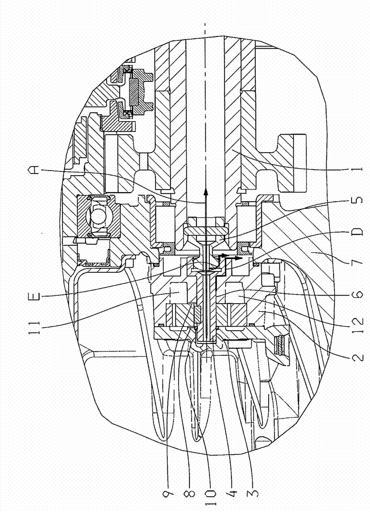
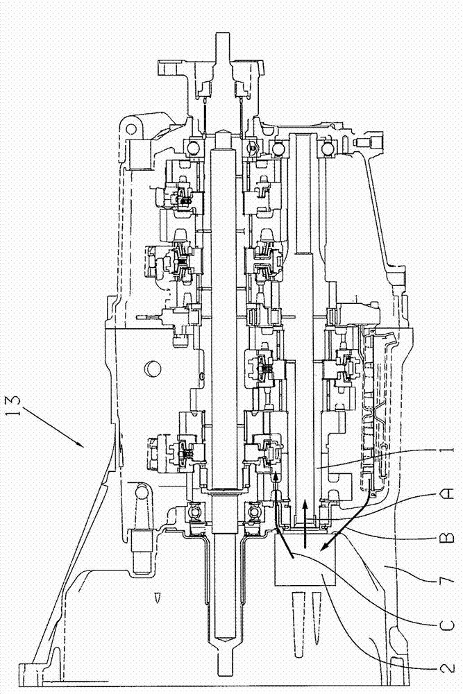
[0024] According to the invention, the internal oiling of the transmission shaft takes place via the already existing leakage oil of an oil pump integrated into the transmission. refer to figure 1 An oil pump 2 flanged to the clutch housing 7 is arranged coaxially with and driven by the transmission shaft 1 to be oiled.

[0025] According to the invention, leakage oil from at least one pump shaft bearing point 3 is guided into the pump shaft 4 which is designed as a hollow shaft and via a carrier which has an internal bore and connects the pump shaft 4 to the transmission shaft 1 to be oiled. 5 is transferred to the transmission shaft 1 which is to be oiled and which also has an inner bore. The leakage oil flow used to oil the inside of the transmission shaft 1 is in the figure 1 Indicated by arrow A.

[0026] In the event that the leakage oil quantity of the at least one pump shaft bearing point 3 is not sufficient for internal oiling of the transmission shaft 1 to be lubr...


PUM


Abstract

The invention relates to a method for the internal oiling of a gear shaft (1) that is arranged coaxially to the oil pump (2) of a gearbox (13) and drives the oil pump (2), wherein the internal oiling of the gear shaft (1) is effected by the existing leakage oil of the oil pump (2) integrated in the gearbox (13).

Description

technical field [0001] The invention relates to a method according to the preamble of claim 1 for the internal oiling of a transmission shaft arranged coaxially to a transmission oil pump and driving the oil pump. Furthermore, the invention relates to a device for oiling the inside of a transmission shaft arranged coaxially to a transmission oil pump and driving the oil pump, in particular for carrying out the method according to the invention. Background technique [0002] Various methods and devices are known from the prior art for oiling the interior of the transmission shaft. The internal oiling of transmission shafts can be carried out, for example, by means of passive oiling systems, in which special oil guides are used which collect the oil by means of drip ribs in the housing or by means of oil collectors and drain the oil via channels. Leading to one end of the transmission shaft to be oiled; the oil is guided into the shaft by means of an oil guide protruding into...

Claims


Application Information

Patent Timeline
Patent Type & Authority Applications(China)
IPC IPC(8): F16H57/04
CPCF16H57/0494F16H57/0436F16H57/043F16H57/0441F01M11/02F01M1/02
Inventor C·尼古拉齐格
Owner ZF FRIEDRICHSHAFEN AG
Why Eureka
Try Eureka