Valve and valve arrangement comprising a plurality of valves

A technology for arranging structure and valve components, which is applied in the direction of valve shell structure, valve operation/release device, valve device, etc., which can solve the problem of large valve shell volume and other problems

Inactive Publication Date: 2016-09-21
ALFMEIER PRAZISION BAUGRUPPEN & SYSTLOSUNGEN
View PDF6 Cites 0 Cited by
  • Summary
  • Abstract
  • Description
  • Claims
  • Application Information

AI Technical Summary

Problems solved by technology

Due to the space required for the printed circuit board, the housing of the valve is correspondingly bulky, which is disadvantageous when installing the valve in tight spaces

Method used


Image

  • Valve and valve arrangement comprising a plurality of valves
  • Valve and valve arrangement comprising a plurality of valves
  • Valve and valve arrangement comprising a plurality of valves

Examples


Embodiment Construction

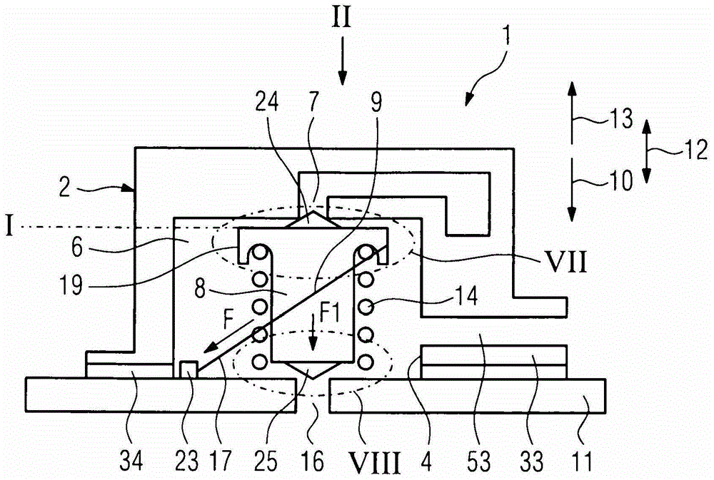
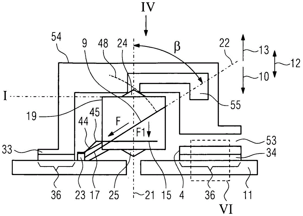
[0033] exist Figures 1 to 4 The valve 1 shown in includes a housing 2 which is formed by a housing cover 3 and a printed circuit board 11 . One side of the housing shell 3 is open, ie an opening 4 is provided in one side of the housing shell 3 , which opening is closed by the printed circuit board 11 . In a valve arrangement 5 formed by a plurality of valves 1 ( Figure 5 ) the openings 4 of the individual valves are blocked by a common circuit board 4a, ie by a subregion thereof. The interior space of the housing 2 formed in this way encloses a pressure chamber 6 . In the housing shell 3 there is a first medium opening 7 which opens into the pressure chamber 6 . A liquid or a gas is considered as medium, wherein the following refers to a pneumatic valve and the medium is air. In the pressure chamber 6 there is a valve element 8 which is movable between a first position I and a second position II in which it closes the first medium opening 7 ( figure 1 and 3 ), in the s...


PUM


Abstract

The invention relates to a valve (1) comprising: a housing (2) surrounding a pressure chamber (6) with a first medium opening (7); a valve element (8) arranged in the pressure chamber, the valve The valve element, which closes the medium opening in a first position (I) and opens the first medium opening in a second position (II), is actuated by at least one wire-shaped SMA element ( 9 ). The valve housing is formed by a housing cover (3) open on one side and a circuit board (11) closing the housing cover, to which the SMA element (9) is electrically connected.

Description

technical field [0001] The invention relates to a valve comprising a housing surrounding a pressure chamber with a first medium opening, wherein a valve element is arranged inside the pressure chamber, which controls the medium opening, ie closes and opens the medium opening . The valve element is actuated by a wire-shaped SMA element. The invention also relates to a valve arrangement comprising a plurality of valves. Background technique [0002] In the valve known from DE 10 2005 060 217 B4, a circuit board is arranged inside the housing, with which the respective ends of a wire-shaped SMA element are electrically and mechanically connected, the SMA element being actuated in the form of a push rod valve components. At one end thereof, the push rod is guided in an opening of the circuit board in the direction of its longitudinal extension. Due to the space required for the printed circuit board, the housing of the valve is correspondingly bulky, which is disadvantageous...

Claims


Application Information

Patent Timeline
Patent Type & Authority Patents(China)
IPC IPC(8): F16K31/02F16K27/02
CPCF16K11/044F16K27/0263F16K31/025Y10T137/86678Y10T137/86686Y10T137/86622Y10T137/86694B60R21/207B60R21/261B60R21/16B60R21/26F16K31/002
Inventor M·科普夫尔M·格布哈德
Owner ALFMEIER PRAZISION BAUGRUPPEN & SYSTLOSUNGEN
Why Eureka
Try Eureka