air dryer

A technology of air drying and air dryer, which is applied in the directions of air treatment device, gas treatment, separation method, etc., to achieve the effect of reducing cost, reducing assembly cost and simplifying structure

Active Publication Date: 2020-10-16
KNORR BREMSE SYST FUER NUTZFAHRZEUGE GMBH
View PDF8 Cites 0 Cited by
  • Summary
  • Abstract
  • Description
  • Claims
  • Application Information

AI Technical Summary

Problems solved by technology

[0007] The inventors have found that, in this construction, the air dryer cartridge is fixed on the air dryer housing in the pressure-free outer area of ​​the air dryer cartridge, but the connection from the air dryer cartridge to the air dryer housing is still only Indirect force flow is possible

Method used


Image

  • air dryer
  • air dryer
  • air dryer

Examples


Embodiment Construction

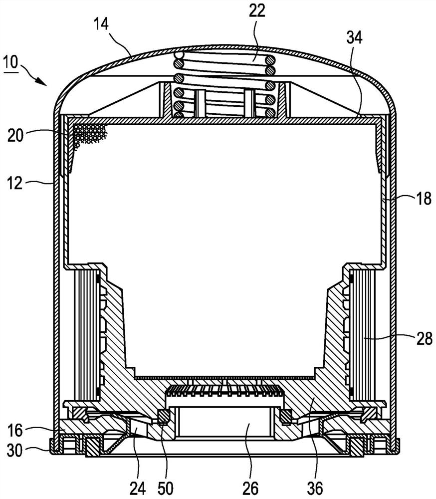
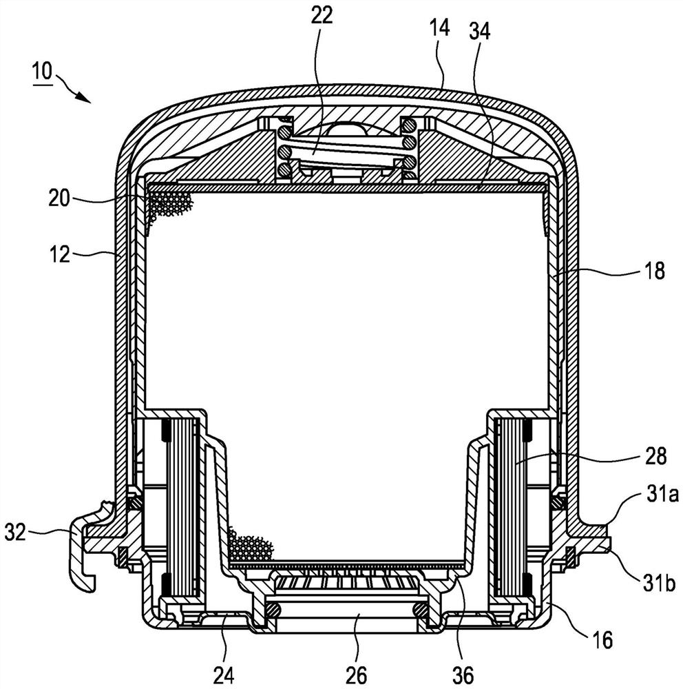
[0036] The invention is explained below in more detail by way of example with the aid of an air drying cartridge for a compressed air treatment device for a commercial vehicle. Components of the air drying cylinder according to the invention correspond to the components of the conventional air drying cylinder shown in FIGS. 1 and 2 and are designated with the same reference numerals, wherein the numeral "1" is added in front of these reference numerals.

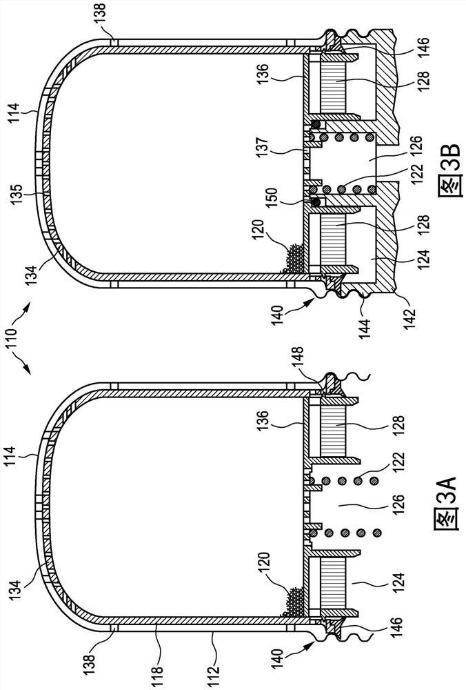
[0037] In Figures 3 and 4, Figure A shows the air drying cartridge itself of the present invention, and Figure B shows the air drying cartridge assembled on the housing of the air dryer, respectively.

[0038] refer to Figure 3A and 3B , first, the air drying cylinder of the first embodiment of the present invention will be explained.

[0039] The air drying cartridge 110 has a substantially cylindrical cartridge housing 112 with a closed housing cover 114 which is formed in the form of a deep-drawn sheet metal. In the end...


PUM


Abstract

The invention relates to an air drying cartridge (110), in particular a compressed air treatment device for commercial vehicles, comprising at least one air inlet (124) and an air outlet (126) and having a housing cover ( 114) in which a desiccant (120) is disposed. The cartridge housing (124) has, in its end region facing away from the housing cover (114), at least one mating section for mating with an anti-mating section (144) on the air dryer housing (142) ( 140 ), so that the force generated on the air drying cylinder ( 110 ), eg by pressure, can be directed into the air dryer housing ( 142 ) with a direct force flow.

Description

technical field [0001] The invention relates to an air drying cartridge, in particular an air drying cartridge for a compressed air treatment device of a commercial vehicle. Background technique [0002] Such compressed air treatment devices or air drying cartridges are used, for example, in commercial vehicles such as trucks and tractors. These commercial vehicles usually have one or more compressed air consumers, such as brake systems or air springs, which must be supplied with compressed air. Compressed air is typically provided by a compressor such as a displacement piston compressor driven by the vehicle's drive motor. In order to ensure trouble-free operation of the compressed air consumer, the compressed air supplied by the compressor often has to be further processed. In the compressor treatment plant provided for this purpose, dirt particles already contained in the intake air as well as oil particles and soot particles which enter the compressed air from the comp...

Claims


Application Information

Patent Timeline
Patent Type & Authority Patents(China)
IPC IPC(8): B60T17/00B01D53/26F15B21/041
CPCB01D53/261B60T17/004B01D53/0415B01D2257/80B01D2259/4566
Inventor K·施尼特格
Owner KNORR BREMSE SYST FUER NUTZFAHRZEUGE GMBH
Why Eureka
Try Eureka