
Dedicated jig for numerical control knife machine

A CNC sharpening machine and special fixture technology, applied in the direction of manufacturing tools, other manufacturing equipment/tools, etc., can solve the problems of insufficient locking force, easy wear, and difficulty in meeting the requirements of drawings, etc., and achieve the effect of high repeat positioning accuracy

Inactive Publication Date: 2013-01-09
XIAMEN TUNGSTEN +1
View PDF16 Cites 15 Cited by
  • Summary
  • Abstract
  • Description
  • Claims
  • Application Information

AI Technical Summary

Problems solved by technology

Among the above three fixed structures, only the screw locking structure has the disadvantages of insufficient locking force, the CNC blade is easy to shift during grinding, and the shape and size are difficult to meet the requirements of the drawings; only the pressure plate fixed structure has the disadvantages of pressing If the tightening force is insufficient, the CNC blade will shift left and right and move back and forth during grinding, and the shape and size cannot meet the requirements of the drawing; if there are both thread locking and pressure plate fixing structures, there is insufficient locking force, and the The left knife belly of the CNC blade is correct, the right knife belly is not ground, and the size is difficult to meet the disadvantages of the drawings; at the same time, in the three structures, the bottom of the blade groove of the fixture is easy to wear, causing the installed CNC blade to tilt left and right , the disadvantage of unequal rear angles on the left and right during grinding; in the three structures, since the vertical surface and the bottom surface of the fixture blade groove form an angle, the angle is to be consistent with the rear angle of the CNC blade, so that the vertical angle of the CNC blade The surface and the vertical surface of the fixture blade groove are matched together, so that the contact mode between the CNC blade and the vertical surface of the fixture blade groove is surface contact, which is not conducive to the repeated positioning of the CNC blade

Method used


Image

  • Dedicated jig for numerical control knife machine
  • Dedicated jig for numerical control knife machine
  • Dedicated jig for numerical control knife machine

Examples


Embodiment Construction

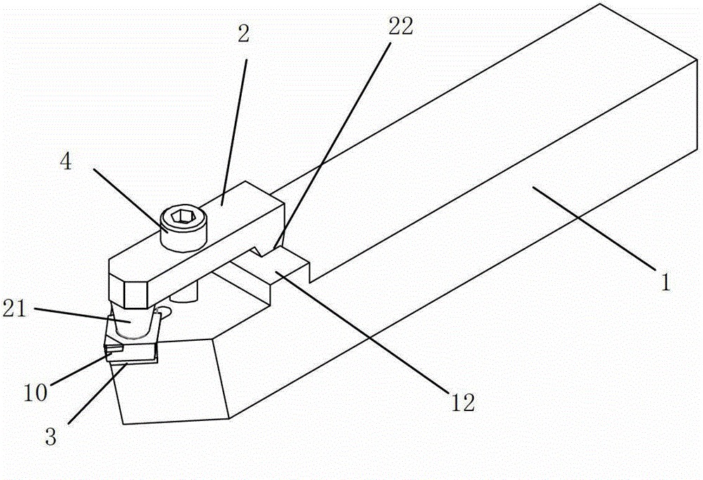
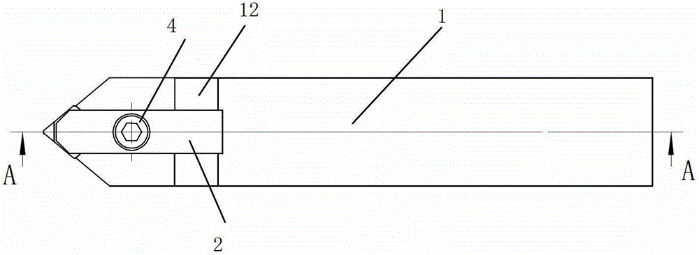
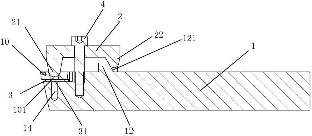
[0026] Embodiment, referring to the accompanying drawings, a special clamp for a CNC knife grinder of the present invention includes a turning handle 1 and a pressing plate 2; the pressing plate 2 is in the shape of a door frame; one end of the turning handle 1 is provided with a blade groove 11, and the blade Groove 11 contains vertical surface 111 and bottom surface 112; The middle of pressing plate 2 is fixed on the turning handle 1 by screw, and one end 21 of pressing plate 2 can press against the numerical control blade 10 of packing into blade groove 11; There is a boss 12 on the top, and the inner hook of the other end 22 of the pressing plate 2 leans against the boss 12 of the turning tool handle. One end 21 of the pressing plate is set as a spherical structure, and one end 21 of the pressing plate is pressed and attached to the insert groove through the spherical structure. CNC blade 10 on.

[0027] It further includes a polycrystalline diamond composite sheet 3, and ...


PUM


Abstract

The invention discloses a dedicated jig for a numerical control knife machine. The dedicated jig comprises a lathe tool handle and a pressure plate; the pressure plate is in a door-frame shape; a cutter blade slot is formed at one end of the lathe tool handle, and the cutter blade slot has a vertical surface and a bottom surface; the middle of the pressure plate is fixed on the lathe tool handle by a screw, and one end of the pressure plate is pressed against a numerical control cutter blade which is placed in the cutter blade slot; a lug boss is arranged in the lathe tool handle, the internal end of the other end of the pressure plate is hooked on the lug boss of the lathe tool handle; one end of the pressure plate is designed into a ball structure; and one end of the pressure plate is pressed and adhered to the numerical control cutter plate which is placed into the cutter blade slot. The structure of the dedicated jig provided by the invention has the characteristics that the locking force is good, the repeated positioning precision is high, the wear resistance degree of the cutter blade slot is high, the flatness and the parallelism are easily ensured, and the sharpening angle of the numerical control cutter blade is easily ensured; and moreover, the consistency of shape and dimension for sharpening processing of the numerical control cutter blade of a super hard cutter tool can be ensured, and the sharpening efficiency and production yield are improved.

Description

technical field [0001] The invention relates to the field of mechanical processing and mechanical manufacturing, in particular to a special fixture for a numerically controlled knife grinder. Background technique [0002] The special fixture for CNC knife grinder is a tool used to clamp the CNC tool. After the CNC tool is clamped by the special fixture for the CNC knife grinder, it is installed on the CNC knife grinder, and the CNC tool can be ground. The existing special fixtures for CNC knife sharpening machines usually include a turning tool handle. One end of the turning knife handle is provided with a blade groove. The CNC tool is usually fixed in the blade groove. There are mainly three types of existing special fixtures for CNC knife sharpening machines. Fixed structure, one is a screw fixed structure, the special fixture for CNC knife grinder with this fixed structure is usually provided with a threaded hole in the blade groove, and the CNC tool can be fixed in the t...

Claims


Application Information

Patent Timeline
Patent Type & Authority Applications(China)
IPC IPC(8): B24B3/00
Inventor 王少武张・格瑞斯・丽颖吴冲浒文晓宋亮周思源董伟石磊
Owner XIAMEN TUNGSTEN
Learn More