Asynchronous door knife of elevator door machine

A technology for elevator door operators and door knives, which is applied in the field of elevator accessories, can solve problems such as poor stability of connecting rods, increased costs, and insufficient clamping of floor door linkage gate balls, etc., and achieves convenient assembly and adjustment, less consumables, and high manufacturing process. simple effect

Active Publication Date: 2014-05-21
SHANGHAI MITSUBISHI ELEVATOR CO LTD
View PDF4 Cites 2 Cited by
  • Summary
  • Abstract
  • Description
  • Claims
  • Application Information

AI Technical Summary

Problems solved by technology

When opening and closing the door, some rely on the form of the door knife travel link to drive the cam to maintain the state of the car door door knife clamping the landing door linkage gate ball of the landing door device. This mechanism is related to the length of the connecting rod and the door opening stroke. When the door is opened very large, the connecting rod is also very long, which not only increases the cost, but also deteriorates the stability of the connecting rod; some asynchronous door blades rely on tension springs or weights to act on the cam to keep the car door door blade clamped to the floor door device In this way, when the reverse thrust of the landing door is large, the tension spring and the weight are not strong enough, and the blade will loosen and cannot clamp the landing door linkage goal ball tightly.

Method used


Image

  • Asynchronous door knife of elevator door machine
  • Asynchronous door knife of elevator door machine
  • Asynchronous door knife of elevator door machine

Examples


Embodiment 1

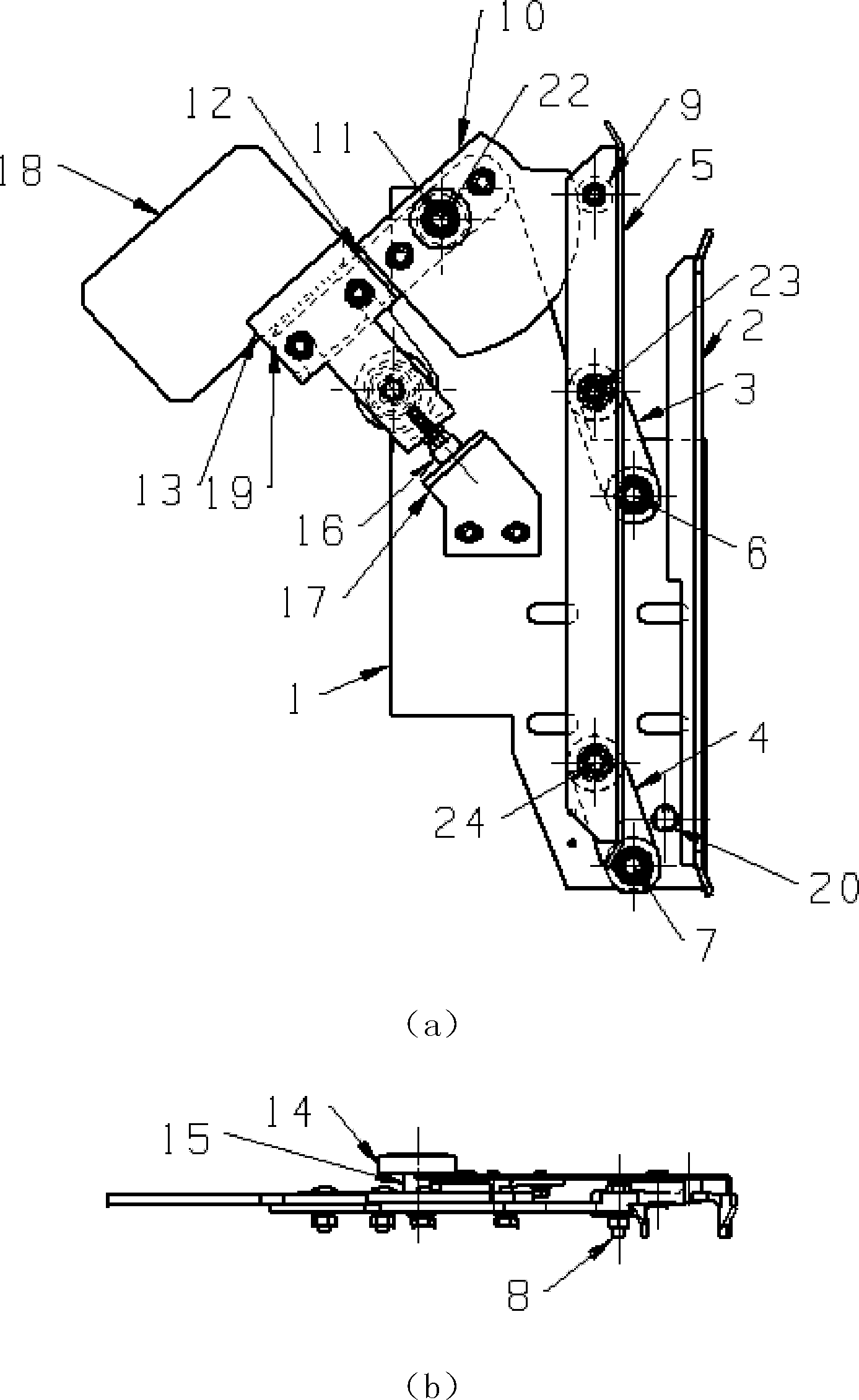
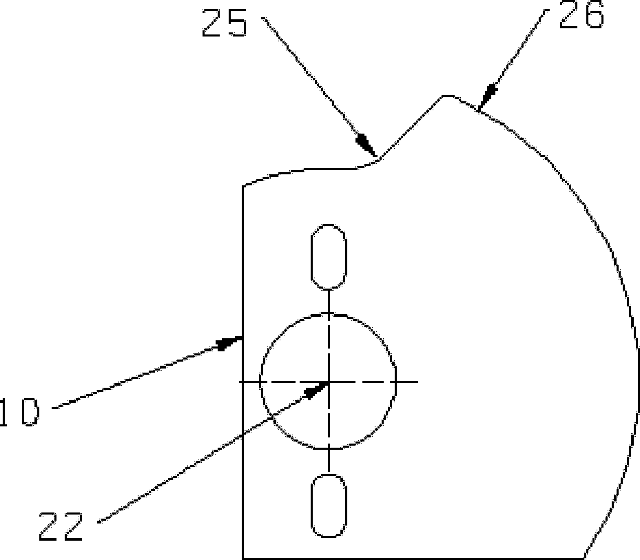
[0040] see figure 1 As shown, the door knife assembly includes: a fixed blade 2, an upper swing rod 3, a lower swing rod 4, a movable blade 5, a roller 9, a first cam 10, a roller 14, a limit screw 16, a baffle 17, Weight 18. in, figure 1 (a) is the front view, figure 1 (b) is figure 1 (a) Top view.

[0041] The fixed blade 2 and the movable blade 5 are arranged in parallel. The fixed blade 2 is installed on the mounting plate 1, and the shaft 6 for the upper swing link, the shaft 7 for the lower swing link and the shaft 11 for the first cam are also installed on the mounting plate 1.

[0042] The upper shaft 23 and the lower shaft 24 are installed on the movable blade 5; the two ends of the upper swing rod 3 are provided with bearings, one end is installed on the upper swing rod shaft 6 of the mounting plate 1, and the other end is installed on the shaft 6 of the movable blade 5. On the upper shaft 23; the two ends of the lower fork 4 are provided with bearings, one end...

Embodiment 2

[0064] As shown in FIG. 9 , the installation and mutual connection relationship of 1 to 26 is the same as that of Embodiment 1, and 32 to 39 are added in this embodiment. First, a shaft capable of installing bearings at both ends is used instead of the shaft 11 for the first cam in the original embodiment 1 to become a common shaft for the first cam and the lever. Manufacture lever 32, there is a round hole in the middle of the lever 32 and a bearing is installed, the center of the round hole is concentric with the center of rotation 22, the lever 32 is installed on the first cam and the lever common shaft 39, the position of the lever 32 is on the mounting plate 1, now the center of rotation of the lever and the center of revolution 22 are concentric. One end of the lever is bent to a certain width, and is pressed against the roller 14 below, and the other end of the lever is provided with a shaft 34 for the roller B, and the roller B is installed on the axle. The second cam...


PUM


Abstract

The invention discloses an asynchronous door knife of an elevator door machine. The clamping action for a landing door linked door ball is realized through the cooperation of a door knife assembly and a cam device, so that the linkage of a carriage door and the landing door can be realized. The door knife assembly is installed on a movable part, and the cam device is installed on a stationary part. In the closing process for opening and closing the linked door, the door knife assembly clamps the landing door linked door ball, and the asynchronous door knife is self-locked, so that the thrusting force for the landing door linked door ball can be continuously and stably supplied; when the door is about to close, the cam device acts on the door knife assembly, a gap needed by the asynchronous door knife and the landing door linked door ball is formed, and the asynchronous door knife is released; and when the door is completely closed, the door knife assembly is subjected to the cam device and cannot produce the action for clamping the landing door linked door ball, and the gap between the door knife assembly and the landing door linked door ball is reliable. The landing door linked door ball is always clamped by the asynchronous door knife in the door closing process, so that a stable drive force is supplied for a landing door.

Description

technical field [0001] The invention relates to an elevator accessory, in particular to an asynchronous door knife of an elevator door machine. Background technique [0002] When the elevator is running up and down, when the car is leveling with the landing, the door knife of the door machine on the side of the car generally drives the door ball on the side of the landing door to be linked together to realize the action of opening and closing the elevator door. [0003] Commonly used door knives include synchronous door knives and asynchronous door knives. The synchronous door knife is that the door knife first realizes the action of clamping the gate ball of the landing door, and then the car door and the landing door are linked together; the asynchronous door knife is that the door knife and the car door move at the same time, before the car door and the landing door are linked. , The car door generally has to go a certain distance first. [0004] At present, the door ma...

Claims


Application Information

Patent Timeline
Patent Type & Authority Patents(China)
IPC IPC(8): B66B13/16
Inventor 江楫
Owner SHANGHAI MITSUBISHI ELEVATOR CO LTD
Why Eureka
Try Eureka