twin turbo internal combustion engine

A technology of internal combustion engines and twin turbines, applied in the direction of machines/engines, non-variable engines, mechanical equipment, etc., can solve problems such as polluting the environment, complex structures, and difficult expansion of structural and space restrictions

Active Publication Date: 2018-01-02
陈名碧
View PDF6 Cites 0 Cited by
  • Summary
  • Abstract
  • Description
  • Claims
  • Application Information

AI Technical Summary

Problems solved by technology

However, since the crankshaft internal combustion engine uses the reverse force of the moment to complete the three auxiliary actions, the loss of efficiency is relatively large.
In addition, since the piston connecting rod of the crankshaft internal combustion engine and the three transmission components of the crankshaft are connected into a "zigzag" structure, when the internal combustion engine does work and explodes with high pressure, the moment arm is not really straightened, but is pushed obliquely, which increases friction and grinding , which greatly reduces the effective use of power. At the same time, the residual heat of the crankshaft internal combustion engine is high, and the heat utilization rate is low. If it is not for the heat dissipation outside the cylinder, the temperature of the residual heat will be higher, and the force arm of the crankshaft internal combustion engine is difficult to expand due to structural and space constraints.
The above reasons cause more than 50% of the energy and fuel to be discharged as exhaust gas, which not only affects the energy conversion rate, but also pollutes the environment, and its power and volume are relatively small
Although the current aircraft turbine internal combustion engine has a high speed, due to its extremely complex structure, the requirements for materials are particularly high, and the energy conversion rate is only about 20%. No matter from the perspective of energy saving or environmental protection, it is urgent to develop new Turbines to change the status quo

Method used


Image

  • twin turbo internal combustion engine
  • twin turbo internal combustion engine
  • twin turbo internal combustion engine

Examples


Embodiment Construction

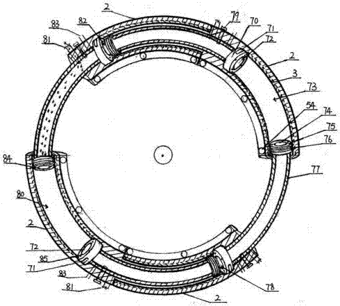
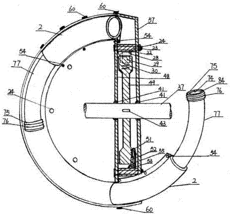
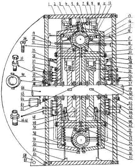
[0008] Such as figure 1 , 2 , shown in 3, the present invention comprises piston, transmission member, connecting member, oil-water-gas supply device and exhaust pipeline, adjustment control member, starter motor 63, clutch wheel 65, clutch wheel key 66, V-belt pulley 64, body circular shell 1. It is composed of several arc-shaped plates connected into one body through shell screws 62. The shell is fixedly connected with the machine base 68. There are fixed screw holes 69 on the machine base. The turbine frame is composed of a turbine disc 57 and a circular steel plate 48. The cylinder The body 2 is arc-shaped, and the cylinder body is provided with an air inlet 81 and an oil inlet 83. The inner ring of the cylinder is connected with the inner circular steel plate through the torx screw 54, and the back is connected with the edge of the turbine disk with the flat head screw 60. The arc cylinder The body is equipped with an arc-shaped inner cylinder liner 3, and each cylinder ...


PUM


Abstract

The invention discloses a twin-turbine internal combustion engine. The twin-turbine internal combustion engine is characterized in that a power shaft is in contact with left and right turbine racks for supporting through a sliding bearing, the power shaft is in contact with a housing through a rolling bearing, the power shaft and a ratchet fly wheel are in bonding through a ratchet fly wheel key, a round steel plate and turbine discs are fixedly connected to arc-shaped cylinders of turbines through screws, a cylinder sleeve is arranged in each cylinder, a piston is mounted at one end of an arc-shaped cylinder of the piston, a piston ring is arranged next to the piston, the other end of the arc-shaped cylinder is propped against a cylinder cover, an exhaust valve is arranged on the cylinder cover, oil injection holes are formed in the periphery of the exhaust valve, an inlet valve is arranged on the piston, and water spray holes are formed in the periphery of the inlet valve. The twin-turbine internal combustion engine disclosed by the invention solves the problem of high internal combustion waste heat and severe pollution. The twin-turbine internal combustion engine is small in noise, small in vibration and long in service life. The power shaft is straight, the output force is steady, the weight of the twin-turbine internal combustion engine is half of that of a crankshaft internal combustion engine, and the effective work can reach 90%.

Description

technical field [0001] The invention relates to internal combustion engine technology, in particular to a twin-turbo internal combustion engine. technical background [0002] The current internal combustion engines mainly include crankshaft internal combustion engines and aircraft turbine internal combustion engines, all of which have three auxiliary work losses of air intake, compression, and exhaust. But because crankshaft internal-combustion engine is to utilize the reverse force of moment to complete three auxiliary actions, the loss effect is bigger. In addition, since the piston connecting rod of the crankshaft internal combustion engine and the three transmission components of the crankshaft are connected into a "zigzag" structure, when the internal combustion engine does work and explodes with high pressure, the moment arm is not really straightened, but is pushed obliquely, which increases friction and grinding , which greatly reduces the effective utilization of p...

Claims


Application Information

Patent Timeline
Patent Type & Authority Patents(China)
IPC IPC(8): F01D1/00
CPCF01D1/00
Inventor 陈名碧
Owner 陈名碧
Why Eureka
Try Eureka