Warp knitting machine

A warp knitting machine and frame technology, applied in the field of warp knitting machines, can solve problems such as increasing the energy consumption of warp knitting machines

Active Publication Date: 2014-10-22
KARL MAYER STOLL R&D GMBH
View PDF6 Cites 0 Cited by
  • Summary
  • Abstract
  • Description
  • Claims
  • Application Information

AI Technical Summary

Problems solved by technology

Temperature adjustment increases the energy consumption of the warp knitting machine

Method used


Image

  • Warp knitting machine
  • Warp knitting machine

Examples


Embodiment Construction

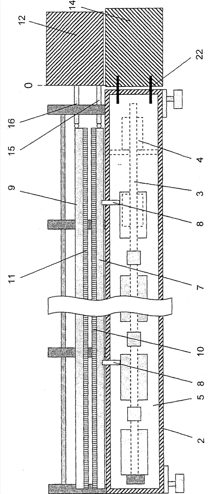
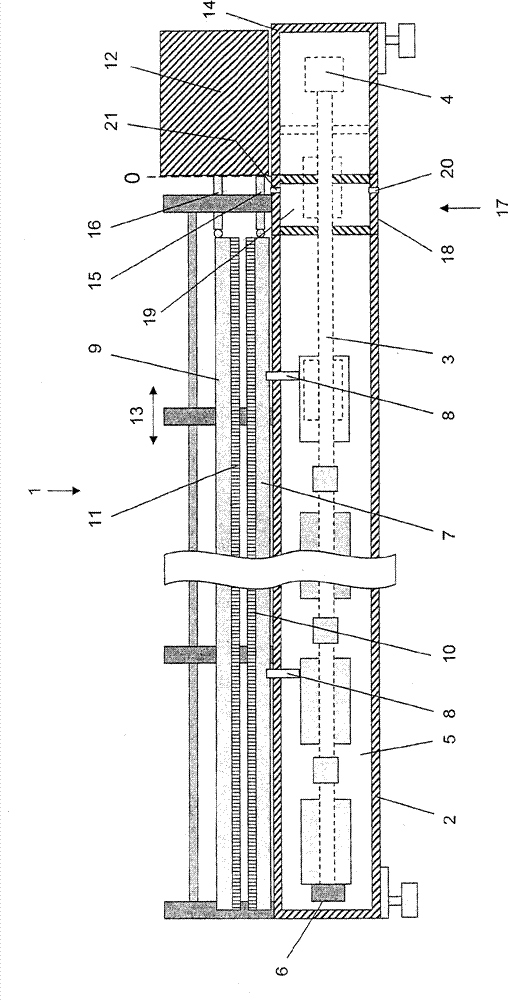
[0021] figure 1 Only briefly and very simplified is shown a warp knitting machine 1 which has a frame 2 in which a spindle 3 is arranged rotatably. The spindle 3 is driven by a drive motor 4 . An oil sump 5 is arranged in the frame 2, from which an oil pump 6 arranged on the main shaft 3 sucks oil in order to lubricate the bearing positions of the main shaft 3 and other moving parts.

[0022] The warp knitting machine 1 has at least two knitting tool holders, namely a needle holder 7 , which is driven by the spindle 3 via a push rod 8 , and a guide needle holder 9 . The knitting needle stand 7 is equipped with many knitting needles 10 side by side. Guide pin holder 9 is equipped with many guide pins 11 side by side. In a manner not shown in detail but known per se, the guide needle holder 9 is likewise driven via the spindle 3 , and the guide needles 11 can vibrate through the interspaces between the knitting needles 10 . In addition, the needle carriage is also driven par...


PUM


Abstract

The machine (1) has a main shaft (3) rotatably supported in a machine bed (2). A patterning device (12), a knitting needle bar (7) and a guide bar (9) are arranged on a carrier (14). The guide bar is translationally movable relative to the patterning device along displacement direction (13) to a zero-point (O) of the patterning device. The needle bar is fixedly positioned along the displacement direction. A thermal decoupling element (17) is arranged between the zero-point and the bed. The carrier and the element are made of material selected from fiber reinforced plastic and mineral casting.

Description

technical field [0001] The invention relates to a warp knitting machine comprising a frame in which a main shaft is arranged rotatably, a jacquard generating device arranged in a support and at least two knitting tool holders, wherein At least one knitting tool holder is movable in translation relative to the zero point of the knitting tool holder in a traversing direction by the jacquard forming device, and at least one other knitting tool holder is fixedly positioned in the traversing direction. Background technique [0002] In a warp knitting machine, the loop forming tools work together to produce a knitted fabric through the loop forming process. For this purpose, there must be at least two needle holders, namely a knitting needle holder and a guide needle holder. The knitting needle bed is equipped with many knitting needles arranged side by side on the width direction of the warp knitting machine. The knitting needle holder is fixedly arranged in the width direction...

Claims


Application Information

Patent Timeline
Patent Type & Authority Patents(China)
IPC IPC(8): D04B35/30D04B27/00
CPCD04B27/24
Inventor K.B.布兰德尔
Owner KARL MAYER STOLL R&D GMBH
Why Eureka
Try Eureka