Secondary optical lens with adjustable beam angle

A technology of secondary optical lens and beam angle, applied in the optical field, can solve the problem of uniform light spot of multi-chip LED.

Inactive Publication Date: 2013-01-09
BEIJING XINGGUANG FILM & TV EQUIP TECH CO LTD
View PDF6 Cites 14 Cited by
  • Summary
  • Abstract
  • Description
  • Claims
  • Application Information

AI Technical Summary

Problems solved by technology

Therefore, this type of secondary optical lens still cannot achieve a uniform eff

Method used


Image

  • Secondary optical lens with adjustable beam angle
  • Secondary optical lens with adjustable beam angle
  • Secondary optical lens with adjustable beam angle

Examples


Example Embodiment

[0024] The content of the invention will be described in detail below with reference to the drawings and specific embodiments.

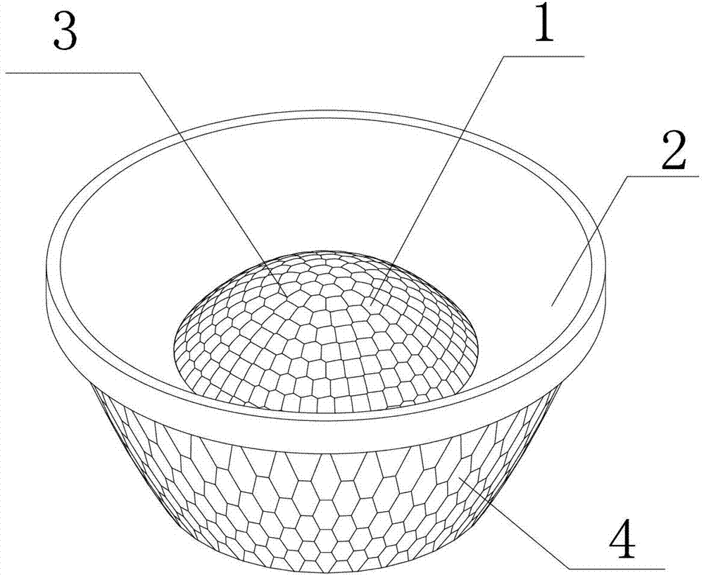
[0025] Such as figure 1 As shown, a secondary optical lens with adjustable beam angle includes a light-condensing part 1 located in the central area of ​​the lens and a total reflection part 2 surrounding the outer edge of the light-concentrating part 1. Among them, when the light-emitting surface center O point of the multi-chip LED is located at the focal position of the secondary optical lens, the light emitted from the light-emitting surface center O point of the multi-chip LED and the light with a small angle with the optical axis OZ will be The light collecting part 1 in the middle collects, converges and mixes light within the range of divergence angle ±Δθ; the light rays with a larger angle with the optical axis OZ are collected by the total reflection part 2 on the outer edge, and are also collected Converge and mix light within the range of di...


PUM


Abstract

The invention provides a secondary optical lens with an adjustable beam angle, capable of enabling a multi-chip LED (Light Emitting Diode) to irradiate uniform light spots. The secondary optical lens comprises a light collecting part in the central zone of the lens and a total reflection part at the periphery of the light collecting part, wherein the upper surface of the light collecting part is a micro lens array formed by a plurality of micro lenses, and the outside reflecting surface of the total reflection part is scale surface formed by a plurality of polyhedron scales. According to the light mixing function performed on the multi-chip LED by the micro lens array of the upper surface of the light collecting part and the polyhedron scales of the outside reflecting surface of the total reflection part, the secondary optical lens can acquire round light spots with even color temperature while changing the beam angle.

Description

technical field [0001] The invention relates to a secondary optical lens, in particular to a secondary optical lens for multi-chip LEDs with adjustable beam angles, and belongs to the field of optical technology. Background technique [0002] Traditional secondary optical lenses are mostly plano-convex or biconvex concentrating lenses with simple structure, without total reflection design. This kind of lens can only be used to adjust the light angle of the single-chip LED, so that it can irradiate uniform light spots in certain positions. When the secondary optical lens is used for multi-chip LEDs, due to the imaging effect of the convex lens, the light spots will show a plurality of regularly arranged square shadows, and when used for three-color LEDs composed of red, green and blue chips, It will project light spots containing color blocks of different colors, which is very unsightly. For this reason, it is necessary to adjust the beam angle through a secondary optical l...

Claims


Application Information

Patent Timeline
IPC IPC(8): F21V5/04F21Y101/02
Inventor 甄何平蒋金波
Owner BEIJING XINGGUANG FILM & TV EQUIP TECH CO LTD
Why Eureka
Try Eureka