
Illuminating device

A technology for lighting devices and optical devices, applied in lighting devices, lighting device parts, lighting and heating equipment, etc., can solve the problems of complex manufacturing process and insertion process, etc.

Inactive Publication Date: 2013-06-12
OSRAM GMBH
View PDF9 Cites 2 Cited by
  • Summary
  • Abstract
  • Description
  • Claims
  • Application Information

AI Technical Summary

Problems solved by technology

However, in this lighting device, a relatively large receiving portion is required to place the inserted fluorescent cover, and the manufacturing process and the inserting process are relatively complicated.

Method used


Image

  • Illuminating device
  • Illuminating device
  • Illuminating device

Examples


Embodiment Construction

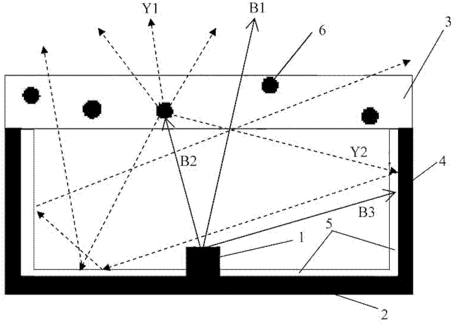
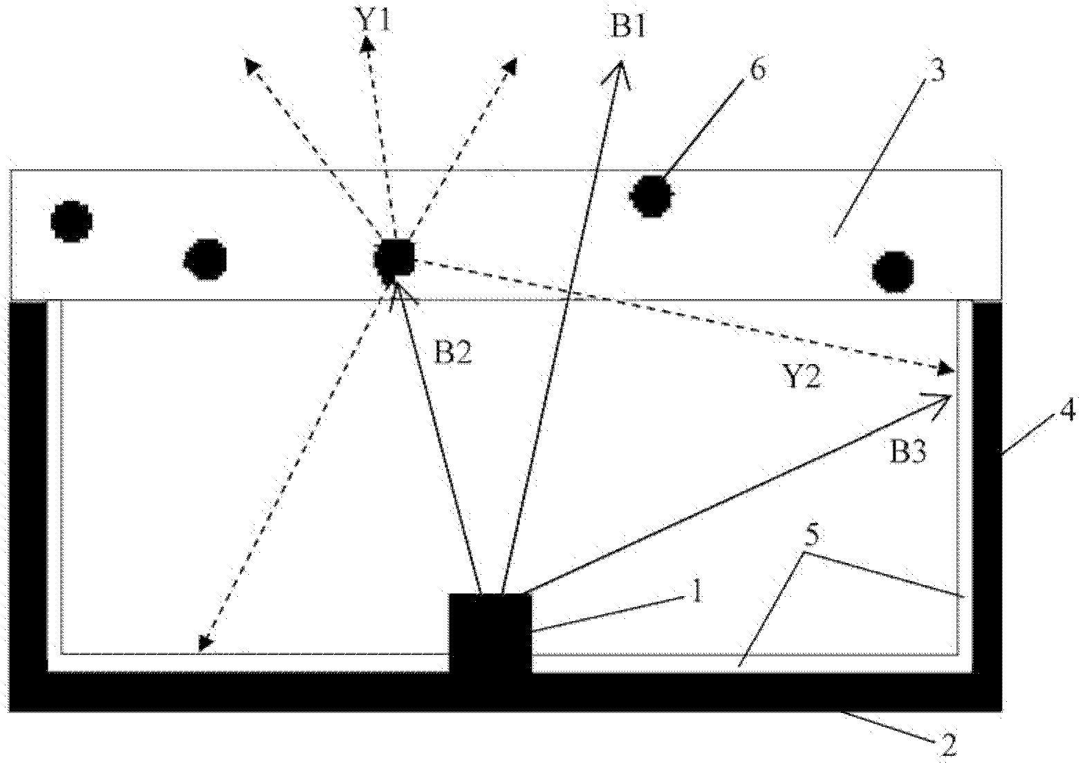
[0025] figure 1 A cross-sectional view of a first embodiment of a lighting device according to the invention is shown. As can be seen from the figure, the lighting device is designed as a closed cylinder, cube or cuboid, for example, including a fluorescent cover 3 as the top surface, a circuit board 2 as the bottom surface, and a cavity R jointly defined by the fluorescent cover 3 and the circuit board 2 4 of the side walls. In the closed cavity R, at least one blue LED chip 1 is installed on the circuit board, the LED chip 1 emits the first part of blue light B1 and the second part of blue light B2 toward the fluorescent cover 3, and the LED chip 1 also emits the third part toward the side wall 4 Blu-ray B3. In the lighting device according to the present invention, the fluorescent cover 3 is made of a light-transmitting material doped with fluorescent particles 6, such as PC, PMMA, etc.; the side wall 4 is made of a light-absorbing material, such as a black porous materia...


PUM


Abstract

The invention relates to an illuminating device. The illuminating device comprises a circuit board (2), a plurality of side walls (4) and a fluorescent cover (3), wherein at least one LED (Light Emitting Diode) chip (1) is arranged on the circuit board (2); the side walls (4) extend out of the circuit board (2); the fluorescent cover (3) is supported on the side walls; and the circuit board (2), the fluorescent cover (3) and the side walls (4) form a cavity (R) for accommodating the at least one LED chip (1). The illuminating device is characterized by further comprising at least one optical device (5) arranged in the cavity (R), wherein the optical device (5) has adjustable reflectivity for adjusting the spectral energy distribution and / or color temperature of emitted light of the fluorescent cover (3). The illuminating device provided by the invention is easy to manufacture, and is compact in structure; and a uniform and continuously-adjustable color temperature can be obtained from a light emitting surface.

Description

technical field [0001] The invention relates to a lighting device. Background technique [0002] With the development of LED lighting technology, more and more people use LED lighting devices as light sources in various environments. For a lighting device with a fixed light source, characteristics of the light output by the light source are usually set, such as spectral power distribution, color temperature (CCT), color rendering index (CRI), and so on. However, in many specific application environments, such as hotels, shopping malls or residential buildings, it is often necessary to adjust the color tone, especially the color temperature, of the output light of the lighting device, so as to change the light atmosphere according to the needs or emotions of users. For example, the lighting device emits warm white light when the user is relaxing, and the lighting device emits cool white light when the user is studying and working. [0003] In the prior art, a fluorescent co...

Claims


Application Information

Patent Timeline
IPC IPC(8): F21S2/00F21V13/00F21Y101/02
CPCF21V14/00F21V14/003F21K9/64F21Y2115/10F21V7/24F21V13/08
Inventor 郑盛梅陈鹏钟传鹏明玉生
Owner OSRAM GMBH
Learn More