Reactor cavity water injection cooling system with combination of active and passive power

A technology for reactor cavity water injection and cooling system, which is applied in cooling devices, reactors, nuclear power generation, etc., can solve the problems of low cooling rate of molten material and long solidification time of molten material, and achieve short solidification time, small space occupation and long-term circulation cooling effect

Active Publication Date: 2013-01-09
CHINA NUCLEAR POWER ENG CO LTD
View PDF7 Cites 23 Cited by
  • Summary
  • Abstract
  • Description
  • Claims
  • Application Information

AI Technical Summary

Problems solved by technology

But because the melt cooling rate is low, the solidifi...

Method used


Image

  • Reactor cavity water injection cooling system with combination of active and passive power

Examples


Embodiment 1

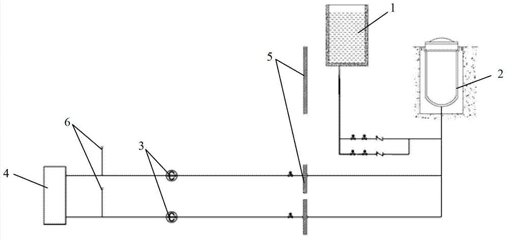
[0024] like figure 1 As shown, the combined active and passive reactor cavity water injection cooling system (CIS) includes a passive reactor cavity water injection tank 1 and two reactor cavity water injection cooling pumps 3, and the passive reactor cavity water injection tank 1 passes through The passive injection pipeline is connected to the reactor cavity 2, the reactor cavity water injection cooling pump 3 is arranged outside the containment 5, the inlet pipe of the reactor cavity water injection cooling pump 3 is connected to the refueling water tank 4, and the outlet of the reactor cavity water injection cooling pump 3 The pipeline runs through the containment vessel 5 and connects with the reactor cavity 2 . The refueling water tank 4 can be installed outside the containment or inside the containment. The preferred solution is to install the refueling water tank in the pit below the core, and the refueling water tank is located at the lowest point, so as to facilitate...

Embodiment 2

[0033] The present invention also provides another active and passive combined reactor cavity water injection cooling system (CIS) structure, the main difference from Embodiment 1 is that the passive reactor cavity water injection tank is arranged outside the containment, which is different from the passive The passive injection pipeline connected to the reactor cavity water injection tank is respectively connected to the outlet pipelines of two reactor cavity water injection cooling pumps. The refueling water tank as the cooling water source may also be placed outside the containment.

[0034] The operation mode and working process of the CIS system in Embodiment 2 are similar to those of the CIS system in Embodiment 1. However, since the passive reactor cavity water injection tank is placed outside the containment, it is no longer possible to supplement the passive reactor cavity water injection tank with steam condensate from the PCS system. Therefore, an external water sup...


PUM


Abstract

The invention belongs to reactor design technology and particularly relates to a reactor cavity water injection cooling system with a combination of active and passive power. The reactor cavity water injection cooling system structurally comprises a passive reactor cavity water injection tank and reactor cavity water injection cooling pumps, the passive reactor cavity water injection tank is connected with a reactor cavity through a passive injection line, the reactor cavity water injection cooling pumps are arranged outside a containment, inlet tubes of the reactor cavity water injection cooling pumps are connected with a refueling water tank, and outlet tube lines of the reactor cavity water injection cooling pumps penetrate through the containment and are connected with the reactor cavity. As a countermeasure for serious accidents, the reactor cavity water injection cooling system has safety functions of taking away reactor core fusant, exhausting reactor core heat and avoiding melting in a multi-redundant and diversified way of combining active power with passive power when the accidents happen.

Description

technical field [0001] The invention belongs to reactor design technology, in particular to a reactor cavity water injection cooling system combining active and passive. Background technique [0002] In nuclear power plants around the world, measures to deal with core melt are divided into two types: one is In-Vessel Retention (IVR), such as the US AP1000 reactor type, under severe accident conditions, when the core melts When unavoidable, the integrity of the lower head of the pressure vessel can be maintained by submerging the reactor cavity and cooling the outer wall of the pressure vessel, thereby retaining the molten core material in the pressure vessel. Cooling the core melt in a passive way has the advantages of simple structure and low cost (but not suitable for high-power nuclear power plants), and the melt can be confined in the pressure vessel, preventing the leakage of radioactive substances and ensuring the integrity of the containment shell. However, since th...

Claims


Application Information

Patent Timeline
IPC IPC(8): G21C15/18
CPCG21C15/182Y02E30/40G21C15/18G21D1/02Y02E30/30
Inventor 于勇袁霞赵侠张国强李京彦宋代勇万砺珂赵斌
Owner CHINA NUCLEAR POWER ENG CO LTD
Why Eureka
Try Eureka