Transformer clamp and mounting method

A technology of transformer clamping and installation methods, which is applied in the direction of inductance/transformer/magnet manufacturing, transformer/inductor coil/winding/connection, electrical components, etc., which can solve the problem of uneven force, high installation labor intensity, and affecting transformer performance and other issues to achieve the effect of improving installation efficiency, reducing installation labor intensity and realizing mechanization

Inactive Publication Date: 2015-06-24
济南西电特种变压器有限公司
View PDF4 Cites 0 Cited by
  • Summary
  • Abstract
  • Description
  • Claims
  • Application Information

AI Technical Summary

Problems solved by technology

[0003] During the assembly process of the transformer, due to the structure of the coil part, during the assembly process, due to the rebound of the coil height or the elasticity of the coil itself, the height of the transformer body is greater than the height required by the theoretical design. Affect the installation of the iron yoke on the transformer core
At the same time, after the installation of the iron yoke on the iron core, in the process of compressing the transformer body, the staff manually operate, the installation is labor-intensive, time-consuming, labor-intensive, low in efficiency, and the force is uneven, which affects the performance of the transformer.

Method used


Image

  • Transformer clamp and mounting method
  • Transformer clamp and mounting method
  • Transformer clamp and mounting method

Examples


Embodiment Construction

[0013] In order to clearly illustrate the technical features of this solution, the present invention will be described in detail below through specific implementation modes and in conjunction with the accompanying drawings.

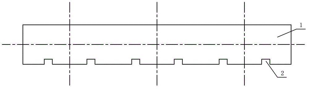
[0014] Such as figure 1 As shown, the present invention includes a transformer body 4 and a clamp body 1, and slots 2 are slotted on the lower side of the clamp body 1 near the coil. There are six slots on the clip body.

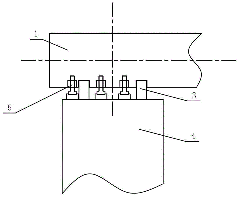
[0015] Such as figure 2 , image 3 As shown, when in use, a transformer installation method, first install the transformer body 4, then install the clamp body 1, fix the transformer clamp body 1 on the upper and lower parts of the transformer body, and tighten it with a tensioning device Fasten, then put the hydraulic device 3 (which can be a part of the oil cylinder or jack) into the space between the clamp body 1 and the coil, and the upper end of the hydraulic device 3 leans against the slot of the clamp body, The other end of t...


PUM


Abstract

The invention discloses a transformer clamp which comprises a clamp body and is characterized in that the lower side of the clamp body, which is near one side of a coil, is provided with slots; one slot is arranged on the left and the right of each phase of the coil; and each clamp body is provided with six slots. By adopting the scheme, the mechanization of the compression of a transformer is realized on the premise of not changing the integral structure of the transformer, so that labor intensity of staffs in site mounting is greatly reduced; the time and labor are saved; and the mounting efficiency is improved.

Description

technical field [0001] This invention relates to improvements in transformer clamps. Background technique [0002] The transformer body refers to the main body of the transformer, namely the core and coil. Oil-immersed transformers usually have a large shell with insulating oil inside, and the body refers to the remaining part after removing the oil and shell. [0003] During the assembly process of the transformer, due to the structure of the coil part, during the assembly process, due to the rebound of the coil height or the elasticity of the coil itself, the height of the transformer body is greater than the height required by the theoretical design. Affect the installation of the iron yoke on the transformer core. At the same time, after the iron yoke is installed on the iron core, in the process of compressing the transformer body, the staff will manually operate the installation. The installation is labor-intensive, time-consuming, labor-intensive, low in efficiency,...

Claims


Application Information

Patent Timeline
Patent Type & Authority Patents(China)
IPC IPC(8): H01F27/30H01F41/00
Inventor 宫来庆张金利杨硕盛振强董丽玲
Owner 济南西电特种变压器有限公司
Why Eureka
Try Eureka