Technology device for magnetic permanent electromotor stator/rotor installation

A technology of process equipment and permanent magnet motors, applied in the direction of electromechanical devices, manufacturing motor generators, electrical components, etc., can solve the problems of time-consuming, labor-intensive, low labor efficiency, high risk, etc., and achieve high efficiency

Inactive Publication Date: 2008-02-13
SHANGHAI ELECTRICAL APP RES INST GRP +1
View PDF0 Cites 17 Cited by
  • Summary
  • Abstract
  • Description
  • Claims
  • Application Information

AI Technical Summary

Problems solved by technology

In the process without special equipment, if the assembly is not handled properly, not only the two will be strongly attracted together and cannot be separated, which will affect the assembly work; even the stator and rotor will be damaged during the forced separation process, and what is more, the In the actual assembly process, personal injury and death accidents caused by finger injury and disability
[0009] At present, all permanent magnet motor manufacturers do not have special equipment for the assembly of permanent magnet motor stator and rotor. Generally, small motors (below 3 ~ 5kW) are assembled by hand, and relatively large motors (above 5kW) are assembled by stator and rotor. All of them are carried out by using hoisting tools such as driving vehicles and other auxiliary tools, which is time-consuming, labor-intensive, labor-inefficient, and dangerous

Method used


Image

  • Technology device for magnetic permanent electromotor stator/rotor installation

Examples


Embodiment Construction

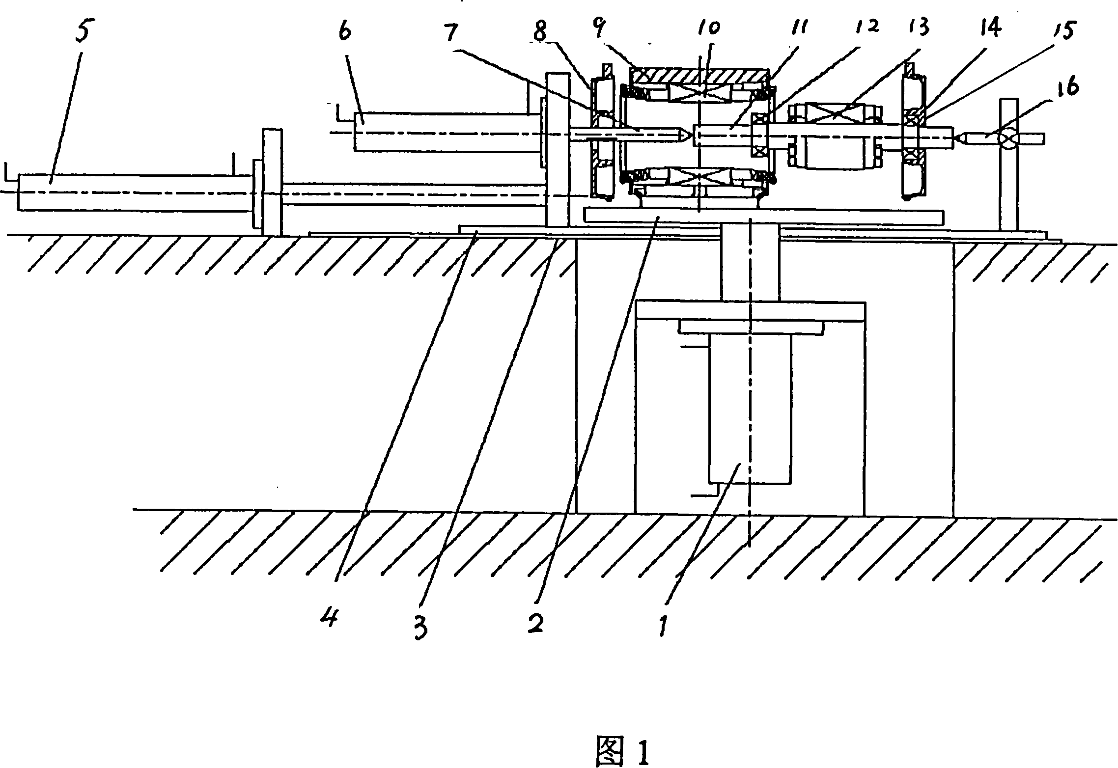
[0015] With reference to Fig. 1, this is the structural representation of the technical equipment used for assembling the stator and rotor of the large-scale permanent magnet motor of the present invention.

[0016] As shown in the figure, the process equipment includes three sets of relatively independent hydraulic systems (hydraulic cylinders) and auxiliary fixtures, guide rails, and trolleys.

[0017] The hydraulic system refers to the working platform lifting hydraulic system 1, the hydraulic cylinder 5, and the clamping hydraulic cylinder 6. The auxiliary tooling fixture includes the front thimble 7, the rear thimble 16, etc.; the relative positions of the parts of the process equipment Yes: hydraulic cylinder 5 and clamping hydraulic cylinder 6 are located on the left side of the process equipment, the front thimble 7 and rear thimble 16 of the auxiliary fixture are located on the right, the working platform 2 and the working platform lifting hydraulic system 1 are locate...


PUM


Abstract

The invention relates to a technological equipment used for assembling of rotors and stators of permanent magnetic motors, which comprises three relatively independent hydraulic systems ( hydraulic cylinders) and auxilliary tools and fixtures, a rack and a trolley. The hydraulic systems ( hydraulic cylinders) are arranged on left side of the technological equipment. The auxilliary tools and fixtures are arranged on the right side of the technological equipment. The rack and the trolley are arranged under the auxilliary tools and fixtures. The hydraulic systems are a lifting hydraulic cylinder, a clamping hydraulic cylinder, a push-and-pull hydraulic cylinder which are relatively independent systems. The height of an operating platform can be adjusted through adjustment of a platform hydraulic system to adapt to the heights of centers of stators of different frame numbers. A thimble of a shaft having a rotor (a front and rear bearing, a rear end cover) is provided with a clamp so that the thimble is clamped. The work trolly is pushed and pulled so that the rotor inserts or pushes a stator in. The auxilliary tools and fixtures comprise a front thimble and a rear thimble and so on. The technological equipment achieves mechanization by replacing human beings to assemble the stators and rotors of the permanent magnetic motors; the efficiency is high; and the utility model works safely and reliably.

Description

technical field [0001] The invention relates to a process equipment for installing a stator and rotor of a permanent magnet motor, which belongs to the technical field of motor manufacturing. Background technique [0002] The motor is currently the most widely used device in electromechanical energy conversion in various countries in the world, and it has a wide range of applications in various fields of the national economy. [0003] In traditional motors, the air-gap magnetic field is generated by current excitation to realize electromechanical energy conversion. In fact, the air-gap magnetic field in the motor for electromechanical energy conversion can be generated by current excitation or by permanent magnets. The first motor in the world was a permanent magnet motor, but the magnetic properties of permanent magnet materials were very low at that time. Low, it was soon replaced by electrically excited motors. [0004] However, in recent decades, with the advent of AlN...

Claims


Application Information

Patent Timeline
Patent Type & Authority Applications(China)
IPC IPC(8): H02K15/00
Inventor 黄力明何定贤
Owner SHANGHAI ELECTRICAL APP RES INST GRP
Why Eureka
Try Eureka