Optic fiber level switch

A liquid level switch and optical fiber technology, which is applied in the field of optical fiber liquid level switches, can solve the problems of decreased accuracy and stability, the surface cannot be kept clean, and the working stability is decreased. Simple and fast effects

Active Publication Date: 2014-11-05
刘信
View PDF4 Cites 0 Cited by
  • Summary
  • Abstract
  • Description
  • Claims
  • Application Information

AI Technical Summary

Problems solved by technology

The commonly used contact optical fiber liquid level switch, because the surface of this kind of detector is required to be clean and undamaged to ensure the inherent surface refractive index of infrared light on the surface of the detector, but the surface cannot be kept clean in the face of oil and sand , when it encounters heavy fog or other bad weather, it will also reduce its working stability, and the refractive index of different oil products is different. When pursuing the diversity of detection objects, the accuracy and stability of the product will decrease.
These products are all closed, and cannot be repaired in case of failure
It can only be replaced, which increases the cost of use and the maintenance period is longer

Method used


Image

  • Optic fiber level switch
  • Optic fiber level switch
  • Optic fiber level switch

Examples


Embodiment 1

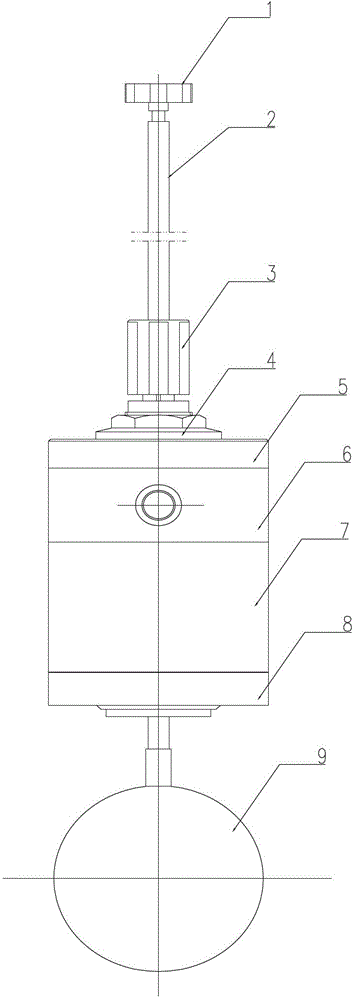
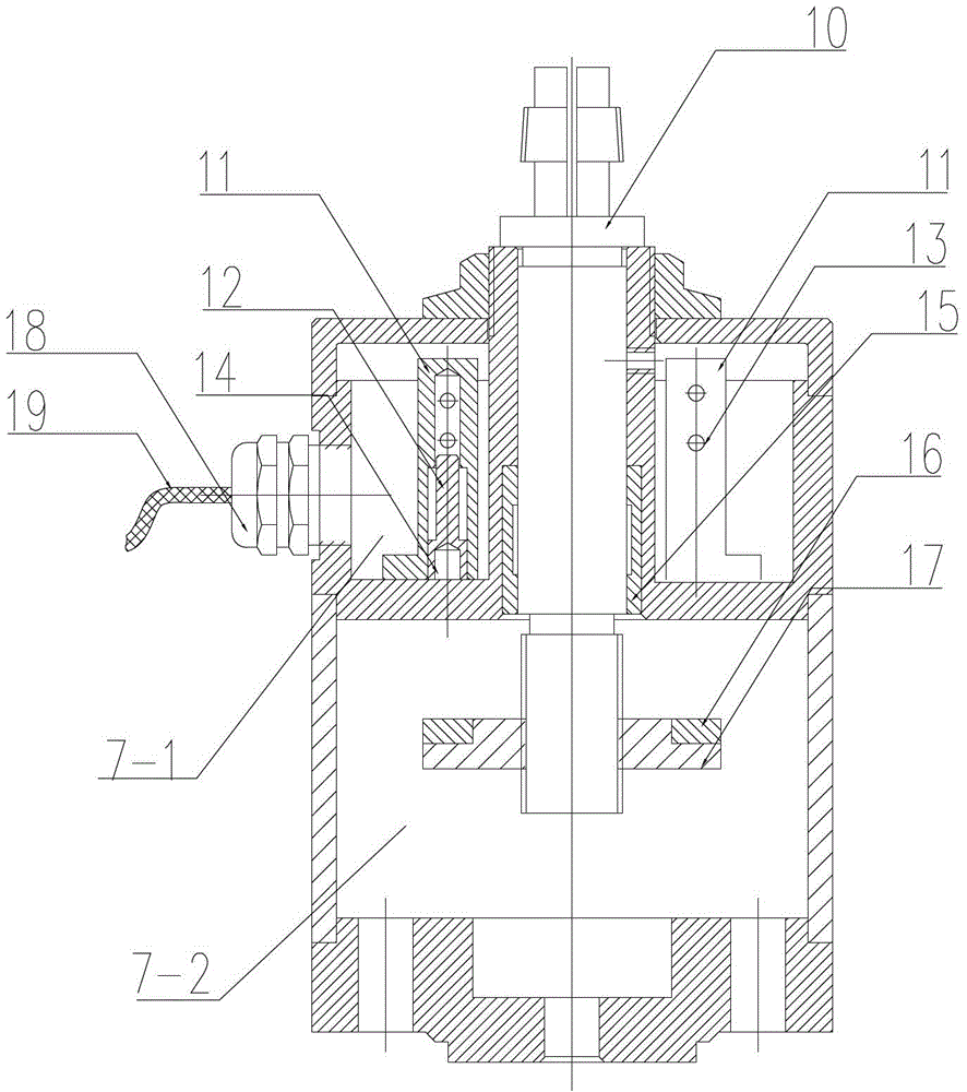
[0032] Example 1: See figure 1 , figure 2 , Figure 5 , Figure 7 As shown, an optical fiber type liquid level switch includes an isolation box 7, a floating ball 9, and a floating ball connecting rod 2. An optical cable clamping joint 18 is provided on the side wall of the isolation box 7, and the floating ball connecting rod 2 The guide post 10 passes through the isolation box 7 and is arranged in a sliding fit with the isolation box 7 and fixed with the guide post 10. A guide sleeve 15 is provided between the contact surface of the guide post and the isolation box, and the float 9 is set in the isolation box. The end of the floating ball connecting rod 2 below 7; the isolation box 7 is divided into an upper cavity 7-1 and a lower cavity 7-2 by a partition; a collimator bracket is provided in the upper cavity 7-1 11. The collimator bracket 11 is provided with a collimator 13 and a light blocking axis 12 for blocking the output of the collimator parallel light, the collimator ...

Embodiment 2

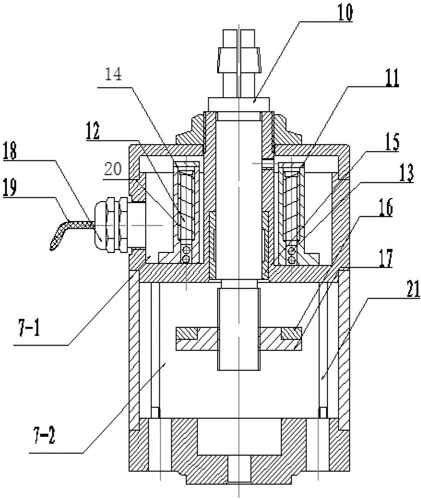
[0035] Example 2: See figure 1 , image 3 , Image 6 , Figure 8 As shown, an optical fiber type liquid level switch includes an isolation box 7, a floating ball 9, and a floating ball connecting rod 2. An optical cable clamping joint 18 is provided on the side wall of the isolation box 7, and the floating ball connecting rod 2 The guide post 10 passes through the isolation box 7 and is arranged in a sliding fit with the isolation box 7 and fixed with the guide post 10. A guide sleeve 15 is provided between the contact surface of the guide post and the isolation box, and the float 9 is set in the isolation box. 7 the end of the floating ball connecting rod 2 below; the isolation box 7 is divided into an upper cavity and a lower cavity by a partition; a collimator bracket 11 is provided in the upper cavity, and the collimator bracket 11 is provided with The collimator 13 and the light-blocking axis 12 for blocking the collimator output parallel light, the light-blocking axis 12 i...

Embodiment 3

[0037] Example 3: Same as Example 2, except that Figure 4 As shown, an optical fiber type liquid level switch includes an isolation box 7, a floating ball 9, and a floating ball connecting rod 2. An optical cable clamping joint 18 is provided on the side wall of the isolation box 7, and the floating ball connecting rod 2 The guide post 10 passes through the isolation box 7 and is arranged in a sliding fit with the isolation box 7 and fixed with the guide post 10. A guide sleeve 15 is provided between the contact surface of the guide post and the isolation box, and the float 9 is set in the isolation box. 7 the end of the floating ball connecting rod 2 below; the isolation box 7 is divided into an upper cavity and a lower cavity by a partition; a collimator bracket 11 is provided in the upper cavity, and the collimator bracket 11 is provided with The collimator 13 and the light blocking axis 12 for blocking the collimator output parallel light, the collimator 13 is arranged belo...


PUM


Abstract

The invention relates to an optical fiber level switch which can be applied to various liquid storage tanks and oil containers and can be used for level detection, site indication signal distant transmission and level alarming switch devices at dangerous places of all kinds of sanitary, toxic and corrosive mediums and explosive gases. The optic fiber level switch comprises an isolation case, a floating ball and a floating ball connection rod; the lateral wall of the isolation case is provided with a cable clamping joint; the floating ball connection rod penetrates through the isolation case by a guide rod, is matched with the isolation case in a sliding way and is fixed with the guide rod; a guide sleeve is arranged between the contact faces of the guide rod and the isolation case; the floating ball is arranged at the end of the floating ball connection rod below the isolation case; the isolation case is internally divided into an upper cavity and the lower cavity through a clapboard; the upper cavity is internally provided with a collimator support; and the collimator support is provided with a collimator and a light shielding device for shielding the collimator to output parallel lights. The optical fiber level switch is simple in structure, stable in physical property, safe and reliable in power-free detection, convenient for mounting, debugging and maintaining and improves the working efficiency and the safety of oil products.

Description

Technical field [0001] The invention relates to various liquid storage tanks or oil filling devices, and can be used in various sanitary, toxic, corrosive media and explosive gas dangerous places for liquid level detection, remote transmission of on-site indication signals, and liquid level alarm switch devices . Background technique [0002] The optical fiber liquid level switch currently used in the market has a contact type, non-adjustable detection part, many faults, poor repairability, short service life, and poor adjustment performance. Can not meet the requirements for use. The commonly used contact type optical fiber level switch, because the surface of this type of detector is required to be clean and undamaged, to ensure the inherent surface refractive index of the infrared light on the surface of the detector, but the surface cannot be kept clean in the face of oil and sand. , When encountering heavy fog or other bad weather, it will also reduce the working stability...

Claims


Application Information

Patent Timeline
Patent Type & Authority Patents(China)
IPC IPC(8): H01H36/02
Inventor 刘信李晓焱尚文博
Owner 刘信
Why Eureka
Try Eureka