
Method for calibrating the water inside the device by using the calibration system of the trace moisture detection device

A technology for a calibration system and a detection device, which is applied in the measurement of color/spectral characteristics, etc., can solve problems such as not being considered, and achieve the effect of convenient waveform adjustment and cost saving.

Inactive Publication Date: 2015-08-26
SHANDONG UNIV
View PDF6 Cites 0 Cited by
  • Summary
  • Abstract
  • Description
  • Claims
  • Application Information

AI Technical Summary

Problems solved by technology

However, the water in the fiber optic gas sensor device has not been considered in this trace water gas detection device.

Method used


Image

  • Method for calibrating the water inside the device by using the calibration system of the trace moisture detection device
  • Method for calibrating the water inside the device by using the calibration system of the trace moisture detection device

Examples


Embodiment 1

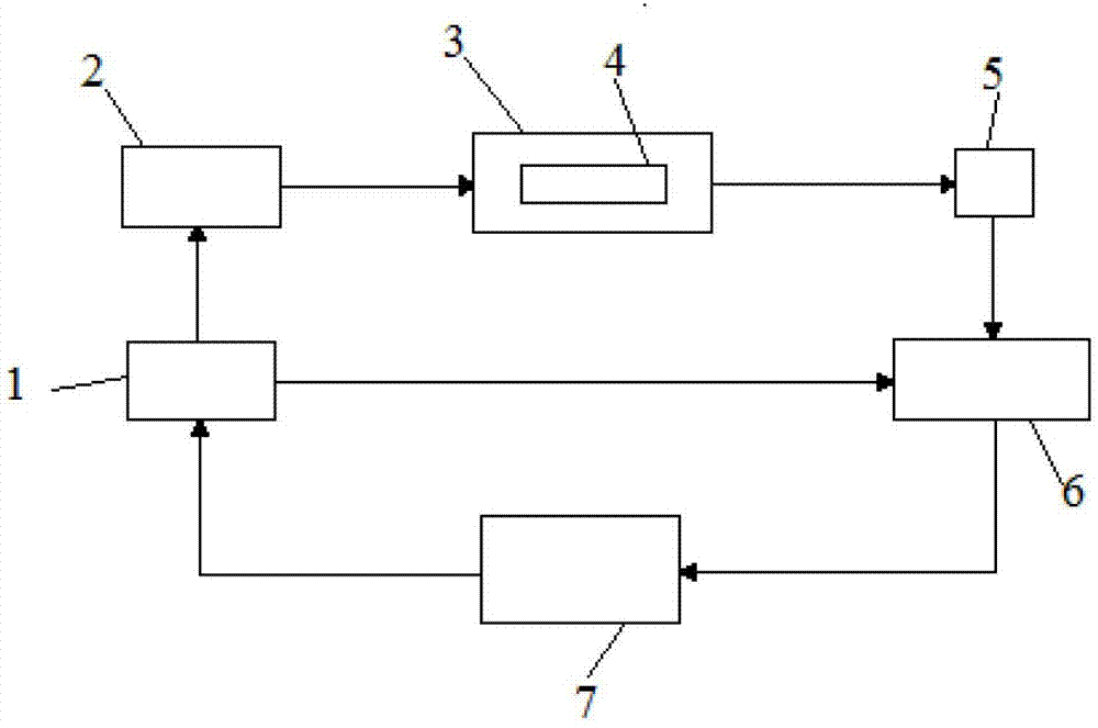
[0034] Embodiment 1 of the device of the present invention is as Figure 1-2 As shown, it includes calibration system, DFB laser 2, gas chamber 3, fiber collimator 4, PIN photodetector 5, differential amplifier circuit 6, filter circuit 7 and single-chip microcomputer 1, which is characterized in that DFB laser 2 is located in front of gas chamber 3 , the fiber collimator 4 is located in the gas chamber 3, the PIN photodetector 5 is located behind the fiber collimator 4, the fiber collimator 4 is coupled to the PIN photodetector 5 through a single-mode fiber connection, and the PIN photodetector 5 outputs terminal is connected to an input terminal of differential amplifier circuit 6, and the output terminal of differential amplifier circuit 6 is connected to filter circuit 7, and the output terminal of filter circuit 7 is connected to the A / D acquisition terminal of single-chip microcomputer 1; Single-chip microcomputer 1 and DFB laser device 2 are connected as It provides the...

Embodiment 2

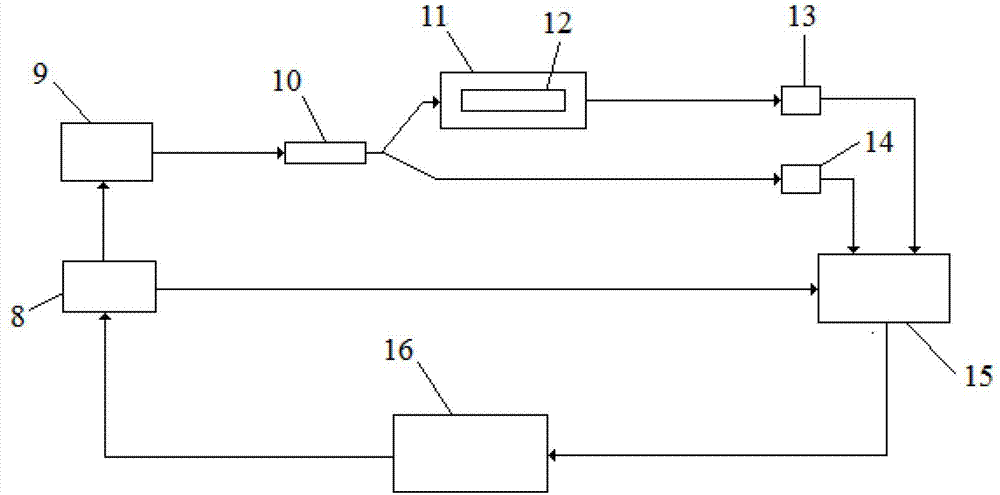
[0037] A method for calibrating the water content inside the device by using the calibration system of the above detection device, the steps are as follows:

[0038] Connect the calibration system; turn on the power of the oscilloscope, turn on the power of the calibration system; debug the optical path and circuit to make it work normally;

[0039] Connect the photoelectric conversion signal of the second PIN photodetector and the trapezoidal wave signal generated by the single-chip microcomputer to the two input terminals of the differential amplifier circuit; adjust the magnification of the photoelectric conversion signal of the second PIN photodetector, and connect it to the second Observe the waveform at the output end of the PIN photodetector until the amplitude of the photoelectric conversion signal of the second PIN photodetector and the slope of the curve are consistent with the trapezoidal wave signal generated by the single-chip microcomputer; the voltage value V...


PUM

PropertyMeasurementUnit
wavelengthaaaaaaaaaa

Abstract

The invention discloses a trace water detecting device by taking water inside a component of an optical fiber gas sensor as a reference, belonging to the technical field of optical fiber detection. The trace water detecting device comprises a calibrating system, a DFB (Distributed Feed Back) laser, an air chamber, a PIN (Personal Identification Number) photoelectric detector, a single chip microcomputer and the like. The calibrating system is used for calibrating the water content inside a device; the DFB laser is located in front of the air chamber; an optical fiber collimator is located in the air chamber; the PIN photoelectric detector is located behind the optical fiber collimator; the output end of the PIN photoelectric detector is connected with one input end of a differential amplification circuit; the output end of the differential amplification circuit is connected with a filter circuit; the output end of the filter circuit is connected with the A / D (Analog-to-Digital) collection end of the single chip microcomputer; the single chip microcomputer is connected with the DFB laser and used for providing driving current for the DFB laser; and the single chip microcomputer is connected to one input end of the differential amplification circuit and used for providing an input signal for the input end of the differential amplification circuit. The device has the advantages of electromagnetic radiation resistance, corrosion resistance and simple technology and is convenient to carry and stable in performance and low in cost.

Description

technical field [0001] The invention relates to a trace water gas detection device using the water inside an optical fiber gas sensor device as a reference, and belongs to the technical field of optical water gas detection. Background technique [0002] Pure SF 6 The gas is a colorless, odorless, non-toxic gas that will not burn, has stable chemical properties, does not chemically react with other substances at room temperature, has non-combustible properties, and is superior to insulating oil, so it has good insulation properties and extinguishing properties. Arc characteristics, under normal conditions, is an ideal insulating medium. SF6 load switch is an excellent load switch experienced by many users in recent years. In addition to having the same advantages as vacuum load switches, such as long electrical life and strong breaking force, its outstanding advantage is that it is easy to realize three working positions (on , disconnection and grounding), small current (in...

Claims


Application Information

Patent Timeline
Patent Type & Authority Patents(China)
IPC IPC(8): G01N21/31
Inventor 常军王强刘永宁王福鹏朱存光魏巍高婷王伟杰
Owner SHANDONG UNIV
Learn More