Fixing device of array laser device

A fixed device and laser technology, applied in the field of lasers, can solve the problems of difficult to meet the strict requirements of array lasers, high cost, and very high processing accuracy requirements, to achieve the requirements of reducing machining accuracy, reduce production costs, and meet optical requirements Effect

Active Publication Date: 2013-01-09
HISENSE
View PDF3 Cites 7 Cited by
  • Summary
  • Abstract
  • Description
  • Claims
  • Application Information

AI Technical Summary

Problems solved by technology

[0008] Therefore, the array laser fixing device in the prior art is generally difficult to meet the strict optical requirements of the array la

Method used


Image

  • Fixing device of array laser device
  • Fixing device of array laser device
  • Fixing device of array laser device

Examples


Embodiment Construction

[0049] In order to make the object, technical solution and advantages of the present invention clearer, the present invention will be further described in detail below with reference to the accompanying drawings and examples.

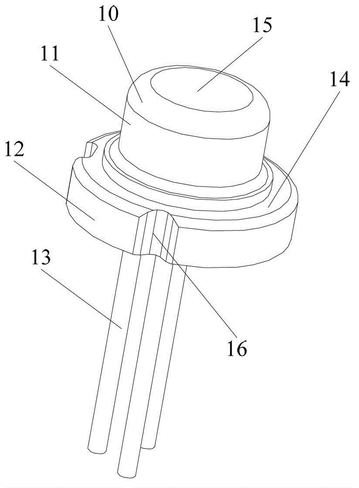
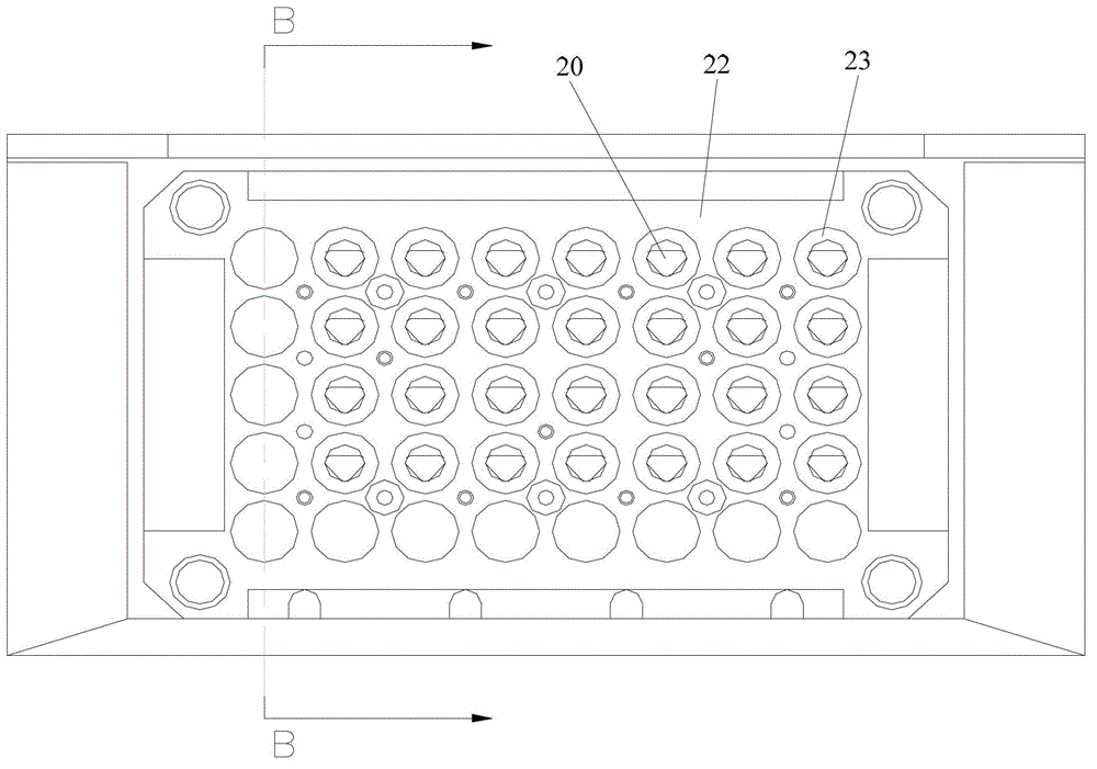
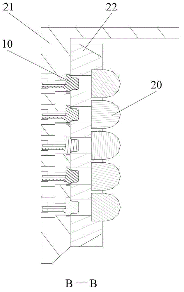
[0050] see Figure 3 to Figure 10 , The fixing device of the array laser in this embodiment includes: a laser base plate 31 , a laser pressure plate 32 , a plurality of mirror holders 33 , a plurality of elastic washers 34 and a mirror holder pressure plate 35 .

[0051] Wherein, the laser bottom plate 31 is provided with a plurality of first through holes 310 through which the pins 13 of the laser 10 can pass, and is also provided with a bottom that surrounds the first through holes 310 and can accommodate the laser 10 12 first step-like structure 311;

[0052]The laser platen 32 is provided with a plurality of second through holes 320 that can pass through the top 11 of the laser 10; the edge of each second through hole 320 is provided with two oppos...


PUM

PropertyMeasurementUnit
Thicknessaaaaaaaaaa

Abstract

The invention discloses a fixing device of an array laser device. The fixing device of the array laser device disclosed by the invention comprises a laser device bottom plate, a laser device pressing plate, a plurality of mirror holders, a plurality of elastic gaskets and mirror holder pressing plates. With the adoption of the fixing device of the array laser device disclosed by the invention, optical requirements of the array laser device can be met and the requirements on the machining precision can be lowered at the same time.

Description

technical field [0001] The invention relates to laser technology, in particular to a fixing device for an array laser. Background technique [0002] In the current projection equipment market, laser light sources are increasingly showing their strong vitality, and more and more manufacturers have launched various laser projection products one after another. As the core of the laser light source, the laser is an essential and important component. In order to achieve high brightness, the existing laser light source generally arranges dozens of lasers in an array to form an array laser, so as to achieve the required brightness requirement. [0003] Array lasers in the prior art are generally composed of multiple lasers, and each laser in the array laser is configured with a collimating lens. In practical applications, array lasers have extremely high requirements on the coaxiality between the laser and the collimating lens, and because the distance between the optical referen...

Claims


Application Information

Patent Timeline
IPC IPC(8): H01S3/02H01S3/23
Inventor 李建春
Owner HISENSE
Why Eureka
Try Eureka