Method for establishing tunnel forwarding table entries, central node and branch nodes
A branch node and central node technology, applied in the field of communications, can solve the problems that the central network cannot send messages from the branch network, the creation of forwarding entries depends on data traffic, and the forwarding efficiency is affected.
- Summary
- Abstract
- Description
- Claims
- Application Information
AI Technical Summary
Problems solved by technology
Method used
Image
Examples
Embodiment 1
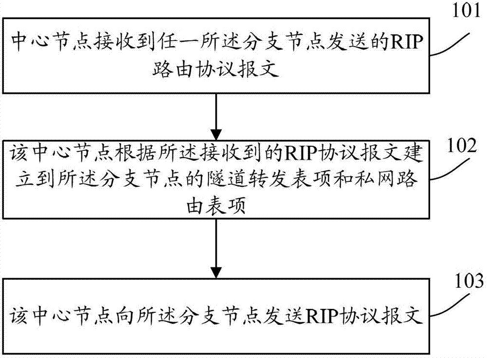
[0061] see figure 1 , figure 1 It is a schematic flowchart of establishing a tunnel forwarding entry in an embodiment of the present invention. The specific steps are:
[0062] Step 101, the central node receives a RIP routing protocol message sent by any branch node.
[0063] After any of the branch nodes enable the RIP routing protocol, because they are in the active mode, they will actively send RIP routing protocol packets to the central node, and the central node will receive the RIP routing protocol packets sent by the branch nodes.
[0064] Step 102, the central node establishes tunnel forwarding entries and private network routing entries to the branch nodes according to the received RIP routing protocol message.
[0065] In this step, the central node uses the outer public network source IP address and the inner layer source IP address carried by the received RIP routing protocol message as the IP address and the tunnel interface IP address used to establish the tu...
Embodiment 2
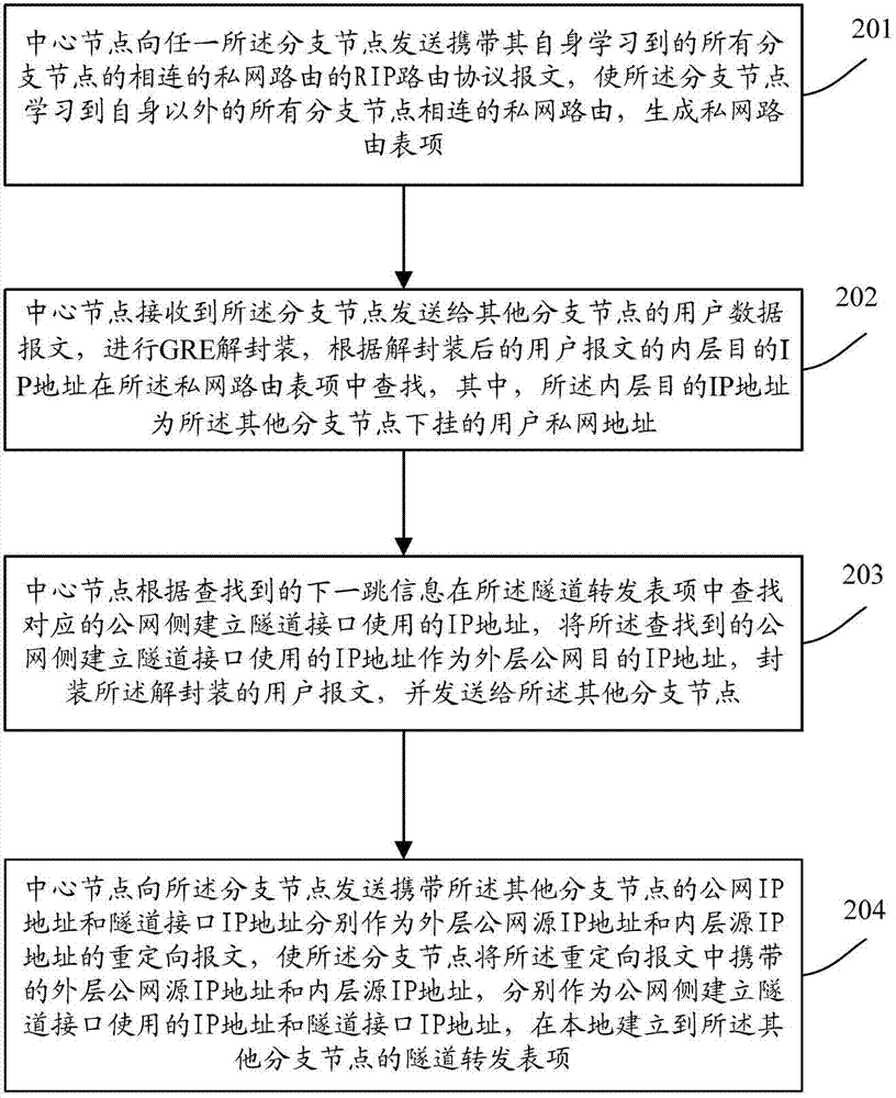
[0074] see figure 2 , figure 2 It is a schematic flowchart of a central node enabling any branch node to establish tunnel forwarding entries to other branch nodes in a specific embodiment of the present invention. The specific steps are:
[0075] Step 201, the central node sends a RIP routing protocol message carrying the connected private network routes of all branch nodes learned by itself to any of the branch nodes, so that the branch node learns the routes connected to all branch nodes other than itself. Private network routing, generate private network routing table entries.
[0076] Step 202, the central node receives the user data message sent by the branch node to other branch nodes, performs GRE decapsulation, and enters the IP address in the private network routing table entry according to the inner layer destination IP address of the decapsulated user message Searching, wherein the inner layer destination IP address is the private network address of the user co...
Embodiment 3
[0081] The following describes in detail how a branch node establishes tunnel forwarding entries to other branch nodes through Embodiment 3 with reference to the accompanying drawings.
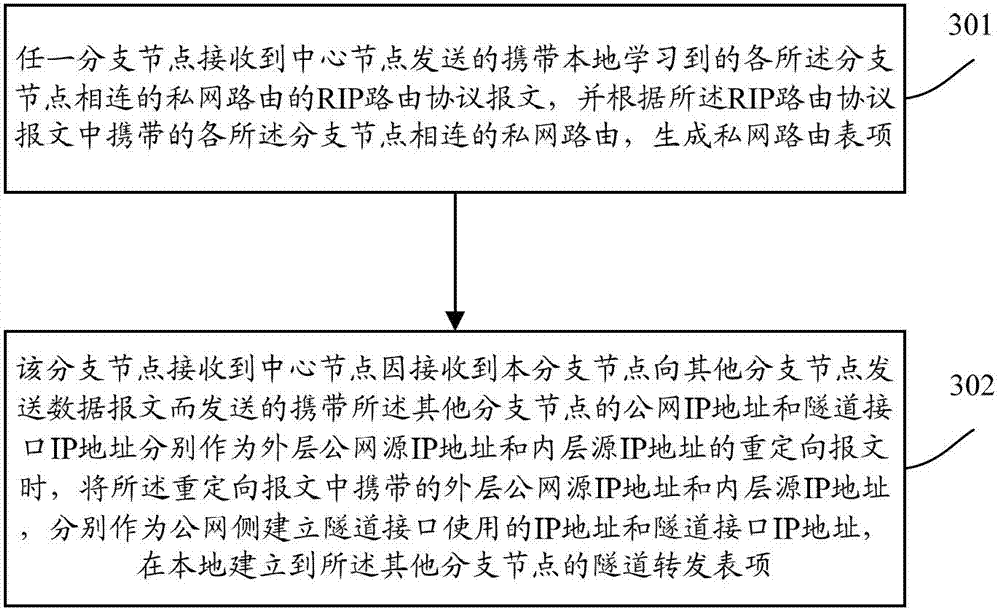
[0082] see image 3 , image 3 Schematic flow chart of establishing tunnel forwarding entries for any branch node to other branch nodes. The specific steps are:
[0083] Step 301, any branch node receives the RIP routing protocol message sent by the central node and carries the locally learned private network routes connected to each of the branch nodes, and according to the RIP routing protocol message carried in each The private network routes connected to the branch nodes generate private network routing table entries.
[0084] In this step, the process of sending the private network route connected to the branch node learned locally by the central node is as follows:
[0085] The branch node sends the RIP routing protocol message carrying the private network route learned locally to th...
PUM
 Abstract
Description
Claims
Application Information
 - R&D
- Intellectual Property
- Life Sciences
- Materials
- Tech Scout
- Unparalleled Data Quality
- Higher Quality Content
- 60% Fewer Hallucinations
Browse by: Latest US Patents, China's latest patents, Technical Efficacy Thesaurus, Application Domain, Technology Topic, Popular Technical Reports.
© 2025 PatSnap. All rights reserved.Legal|Privacy policy|Modern Slavery Act Transparency Statement|Sitemap|About US| Contact US: help@patsnap.com


