Light-emitting diode (LED) drive power supply device

A technology of LED driving and power supply device, applied in electric light source, lighting device, electric lamp circuit layout and other directions, can solve the problems of large output low frequency ripple, slow voltage drop at the output end of LED driving power supply, affecting the working efficiency of LED driving power supply, etc. , to achieve the effect of improving work efficiency, reducing voltage drop time, and reducing afterglow phenomenon

Inactive Publication Date: 2013-01-09
SHENZHEN COLLESUN LIGHTING
View PDF5 Cites 11 Cited by
  • Summary
  • Abstract
  • Description
  • Claims
  • Application Information

AI Technical Summary

Problems solved by technology

At present, the most widely used driving power supply for LEDs is "unipolar PFC". This driving method has the advantages of high efficiency, high power factor, small harmonics, and low cost; , in order to be able to solve the problem of large ripple, the commonly used technology is to add a capacitor with a large capacity at the output end for filtering to reduce the ripple to a very small level, but the filter capacitor will store a lot of energy after power off, making the LED The output voltage of the driving power supply drops slowly, causing the LED light to remain on for a period of time after the switch is turned off, that is, the afterglow phenomenon
[0003] In order to solve the afterglow phenomenon after the switch of the LED lamp is turned off and reduce the afterglow time, in the prior art, a load is generally added to the output end of the LED drive power supply, so that the energy discharge on the filter capacitor can be accelerated; but the newly added load includes The load resistance of the LED drive power supply is always in working condition in the circuit of the LED drive power supply, which greatly affects the working efficiency of the LED drive power supply

Method used


Image

  • Light-emitting diode (LED) drive power supply device
  • Light-emitting diode (LED) drive power supply device

Examples


Embodiment Construction

[0020] The present invention will be further described below in conjunction with the accompanying drawings and embodiments.

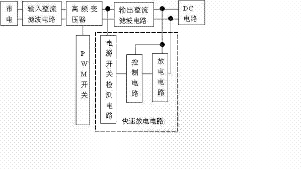
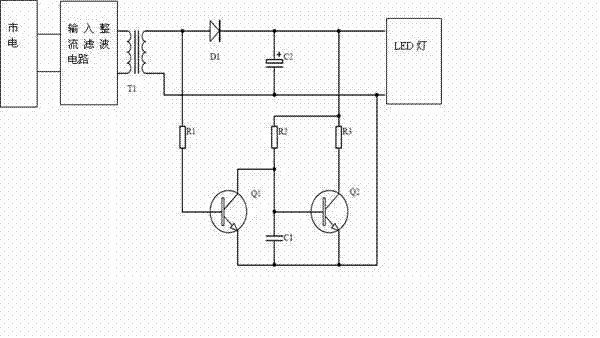
[0021] Refer to attached figure 1 And attached figure 2 As shown, the present invention provides a LED drive power supply device, which is used to quickly discharge the large capacitor at the output end of the LED drive power supply; the device mainly includes an input rectification filter circuit, a high frequency transformer, a PWM switch, an output rectification filter circuit and a DC circuit; It also includes a fast discharge circuit, which includes a power switch detection circuit, a control circuit and a discharge circuit; one end of the power switch detection circuit is connected between the high-frequency transformer and the output rectifying and filtering circuit, and the other end is connected to The control circuit collects and provides switch signals; the control circuit performs logic control according to the switch signals provided by t...


PUM


Abstract

The invention discloses a large capacitance rapid discharge device of a light-emitting diode (LED) drive power supply output end and belongs to the technical field of LED drive power supply. The device mainly comprises an input/output rectifier filter circuit, a high-frequency transformer, a pulse-width modulation (PWM) switch, a direct current (DC) circuit and a rapid discharge circuit, the rapid discharge circuit comprises a power supply switch detection circuit, a control circuit and a discharge circuit, one end of the power supply switch detection circuit is connected between the high-frequency transformer and the output rectifier filter circuit, the other end of the power supply switch detection circuit is connected with the control circuit, the power supply switch detection circuit acquires and provides a switching signal, and the control circuit performs logic control according to the switching signal provided by the power supply switch detection circuit to determine whether the discharge circuit is connected or not. According to the light-emitting diode (LED) drive power supply device, energy on large capacitance can be rapidly released, problems of afterglow and efficiency loss caused by slow discharge are solved, when the LED drive power supply is in normal operation, a load resistor is in a non-operating state, and thereby the influence on the work efficiency of the LED drive power supply is absent.

Description

technical field [0001] The invention relates to the technical field of LED driving power supply, in particular to a large-capacitance rapid discharge device for the output terminal of the LED driving power supply. Background technique [0002] With the rapid development and application of LED technology, LED drive power, as an important part of LED light display, has been increasingly valued; most LEDs on the market are driven by DC power, so LED drive power is mostly based on switching DC voltage sources used. At present, the most widely used driving power supply for LEDs is "unipolar PFC". This driving method has the advantages of high efficiency, high power factor, small harmonics, and low cost; , in order to be able to solve the problem of large ripple, the commonly used technology is to add a capacitor with a large capacity at the output end for filtering to reduce the ripple to a very small level, but the filter capacitor will store a lot of energy after power off, ma...

Claims


Application Information

Patent Timeline
Patent Type & Authority Applications(China)
IPC IPC(8): H05B37/02
CPCH05B45/3725Y02B20/30
Inventor 刘杰黄鹤鸣
Owner SHENZHEN COLLESUN LIGHTING
Why Eureka
Try Eureka