Novel centrifugal pump
A centrifugal pump, a new type of technology, applied in the field of centrifugal pumps, can solve the problems of being unable to temporarily change the flow rate in an emergency, difficult to meet the emergency response to difficult living environments, etc., and achieve the effect of huge market application potential, simple structure, and novel ideas
- Summary
- Abstract
- Description
- Claims
- Application Information
AI Technical Summary
Problems solved by technology
Method used
Image

Examples
Embodiment Construction
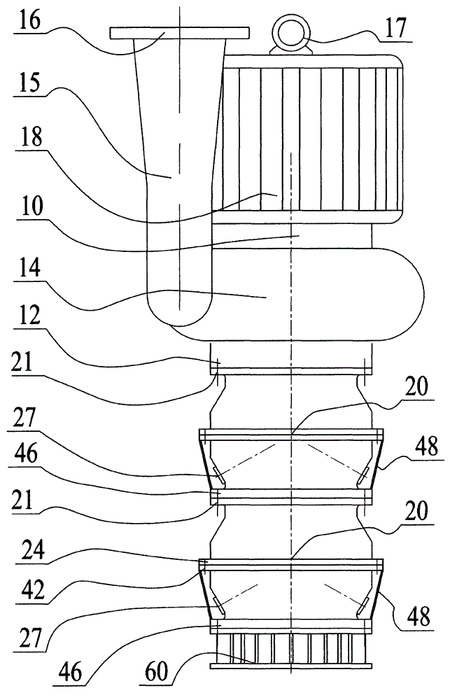
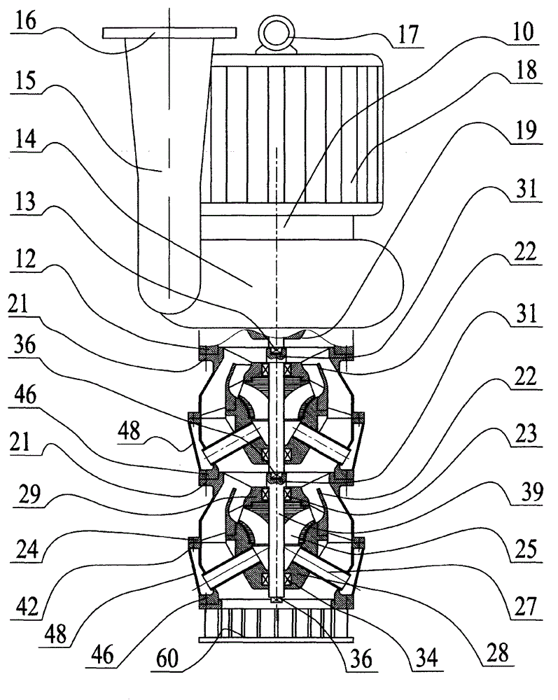
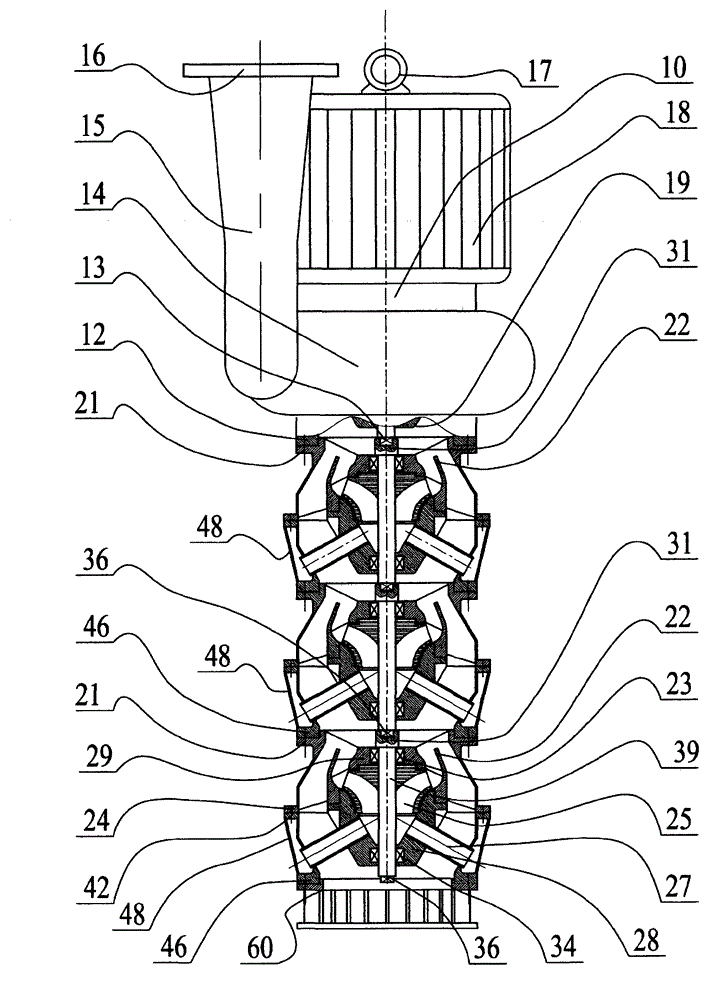
[0026] exist figure 1 , figure 2 , Figure 5 , Figure 6 , Figure 8 and Figure 10 Among them, a new type of centrifugal pump, the waterproof frequency conversion motor 18 is directly connected to the main pump 10, and there are 1 to 3 intermediate pumps 20 between the main pump suction port 12 and the fence filter 60. As an improvement: the intermediate pump 20 is divided into the above The pump casing 75 and the lower pump casing 26; the upper pump casing 75 is connected to the upper pump inner frame 29 through 3 to 6 support ribs 88, and there is an annular isolation seat 22 between the upper pump inner frame 29 and the upper pump casing 75 Cross-connected with the support ribs 88, the inner hole of the upper pump inner frame 29 is also fixed with the outer circle of the upper bearing 23; the lower pump casing 26 is connected to the lower pump inner frame 28 through 3 to 6 suction pipes 27, The outer circle of the lower bearing 34 is also fixed in the inner hole of t...
PUM
 Abstract
Description
Claims
Application Information
 - R&D
- Intellectual Property
- Life Sciences
- Materials
- Tech Scout
- Unparalleled Data Quality
- Higher Quality Content
- 60% Fewer Hallucinations
Browse by: Latest US Patents, China's latest patents, Technical Efficacy Thesaurus, Application Domain, Technology Topic, Popular Technical Reports.
© 2025 PatSnap. All rights reserved.Legal|Privacy policy|Modern Slavery Act Transparency Statement|Sitemap|About US| Contact US: help@patsnap.com