Lubricating direct-current reducing motor

A DC geared motor, geared motor technology, applied in the direction of gear lubrication/cooling, electrical components, electromechanical devices, etc., to improve work efficiency, prevent splashing, and save costs

Inactive Publication Date: 2013-01-16
沈文伟
View PDF0 Cites 0 Cited by
  • Summary
  • Abstract
  • Description
  • Claims
  • Application Information

AI Technical Summary

Problems solved by technology

[0003] In order to overcome the deficiency that the gearbox of the geared motor cannot b

Method used


Image

  • Lubricating direct-current reducing motor

Examples


Embodiment Construction

[0010] The present invention is described in further detail now in conjunction with accompanying drawing. These drawings are all simplified schematic diagrams, which only illustrate the basic structure of the present invention in a schematic manner, so they only show the configurations related to the present invention.

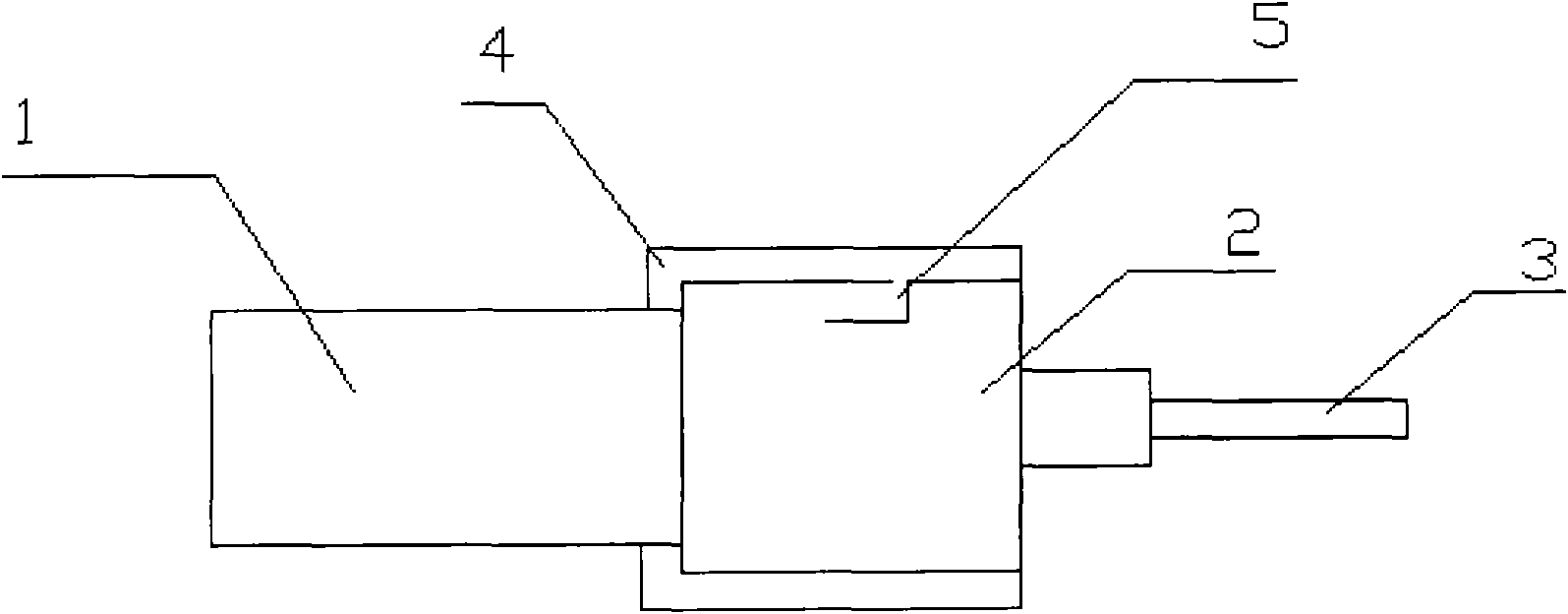
[0011] Such as figure 1 It is a structural schematic diagram of the present invention, including a motor 1, a gearbox 2, a shaft joint 3 and a machine casing 4, the motor 1 is fixed on one side of the gearbox 2, the shaft joint 3 is fixed on the other side of the gearbox 2, and the machine casing 4 The shaft joint 3 is nested on the gearbox 2, and is positioned and connected with the gearbox. An oil guide groove 5 is arranged on the gearbox 2 of the geared motor, and the oil guide groove 5 is concave.

[0012] During work, the lubricating oil is infiltrated into the gearbox 2 through the oil guide groove 5, and the gears in the gearbox 2 are lubricated and ma...


PUM


Abstract

The invention relates to a reducing motor, in particular to a lubricating direct-current reducing motor. The lubricating direct-current reducing motor comprises a motor, a gearbox, a shaft adapter and a motor housing, wherein the motor is fixed on one side of the gearbox; the shaft adapter is fixed on the other side of the gearbox; the motor housing penetrates through the shaft adapter, is nested on the gearbox and is in positioning connection with the gearbox; and an oil guide groove is formed on the gearbox of the reducing motor. By using the reducing motor, lubricating oil can be filled through the oil guide groove in the gearbox at any time, so that gears in the gearbox can be maintained; and the lubricating oil can be prevented from spilling, the work efficiency is improved, and the cost is reduced.

Description

technical field [0001] The invention relates to a geared motor, in particular to a lubricable DC geared motor. Background technique [0002] The gearbox of the original reduction motor is a closed structure, and the internal gears are prone to rust after a long time of use, which affects the normal operation of the reducer. Contents of the invention [0003] In order to overcome the deficiency that lubricating oil cannot be added to the gearbox of the geared motor, the present invention provides a lubricable DC geared motor. [0004] The technical solution adopted by the present invention to solve the technical problem is: a lubricable DC geared motor, including a motor, a gearbox, a shaft joint and a casing, the motor is fixed on one side of the gearbox, and the shaft joint is fixed on the side of the gearbox On the other side, the machine casing is nested on the gearbox through the shaft joint, and is positioned and connected with the gearbox. An oil guide groove is arr...

Claims


Application Information

Patent Timeline
IPC IPC(8): F16H57/04H02K7/116
Inventor 沈文伟
Owner 沈文伟
Why Eureka
Try Eureka