Dimming adapter

A technology of adapters and dimmers, applied to lighting devices, components of lighting devices, circuit layout, etc., to achieve the effects of simple structure, practicality, convenience, portability and use

Inactive Publication Date: 2013-01-16
SHANGHAI TCM INTEGRATED HOSPITAL
View PDF0 Cites 0 Cited by
  • Summary
  • Abstract
  • Description
  • Claims
  • Application Information

AI Technical Summary

Problems solved by technology

However, if the existing lamps such as desk lamps without dimming function are to be dimmed, it will be inconvenient

Method used


Image

  • Dimming adapter
  • Dimming adapter

Examples


Embodiment Construction

[0014] The present invention will be further described below in conjunction with accompanying drawing:

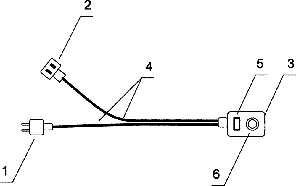
[0015] figure 1 Among them, the dimmer 3 is respectively connected to the power plug 1 and the electrical socket 2 through the wire 4, the dimmer 3 is provided with a power switch 5 and a dimming knob 6, the power plug 1 is a two-wire plug, and the electrical socket 2 is a two-hole socket.

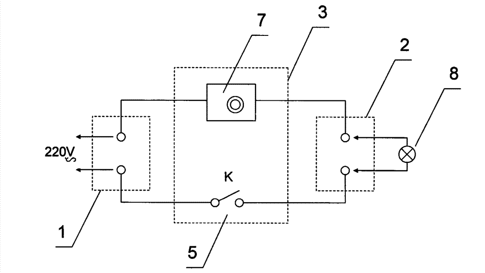
[0016] figure 2 Among them, one wire inside the dimmer 3 is connected to the power switch 5 for controlling power on and off, and the other wire is connected to the dimming circuit module 7 for dimming.

[0017] The method of use is as follows: Insert the power plug 1 of this dimming adapter into a 220V AC power socket, insert the plug of the lamp 8 that needs to be dimmed into the electrical socket 2, turn on the power switch 5 on the dimmer 3, and adjust the dimmer as needed. The light knob 6 realizes the brightness adjustment of the lamp 8 . If you want to turn off the light fix...


PUM


Abstract

The invention discloses a dimming adapter, which consists of a power plug, an electric appliance socket and a dimmer, wherein the dimmer is connected with the power plug and the electric appliance socket respectively through wires; a power switch and a dimming button are arranged on the dimmer; the power plug is a two-wire plug; and the electric appliance socket is a two-hole socket. The dimming adapter is simple in structure, is practical and convenient, is convenient to carry and use and is particularly suitable for dimming lamps such as a desk lamp and a floor lamp.

Description

technical field [0001] The invention relates to a dimming device, in particular to a dimming adapter. Background technique [0002] At present, there are various dimmable lamps on the market, which bring convenience to people's work and life lighting, and are also conducive to low-carbon and energy-saving. However, if existing light fixtures such as desk lamps without a dimming function are to be dimmed and transformed, it will be inconvenient. Contents of the invention [0003] The purpose of the present invention is to provide a dimming adapter, which can conveniently convert a lamp plugged into the dimming adapter into a dimmable lamp. [0004] In order to solve the above technical problems, the present invention is realized through the following technical solutions: [0005] A dimming adapter, which is composed of a power plug, an electrical socket and a dimmer, the dimmer is respectively connected to the power plug and the electrical socket through wires, and the di...

Claims


Application Information

Patent Timeline
IPC IPC(8): F21V23/04F21V23/06
Inventor 谢心吴坚竺春玲邵筱宏丁亚琴
Owner SHANGHAI TCM INTEGRATED HOSPITAL
Why Eureka
Try Eureka