Roots flowmeter

A waist wheel flowmeter and waist wheel technology, applied in the field of flow meters, can solve the problems of mechanical seal coupling complex results, inconvenient installation and use, transmission energy loss, etc., to improve measurement accuracy and sensitivity, not easy to loose, The effect of avoiding corrosion

Inactive Publication Date: 2013-01-16
HEFEI JINGDA INSTR
View PDF5 Cites 3 Cited by
  • Summary
  • Abstract
  • Description
  • Claims
  • Application Information

AI Technical Summary

Problems solved by technology

[0005] The purpose of the present invention is to make up for the deficiencies of the prior art, and to provide a waist wheel flowmeter, which adopts inner and outer magnetic steel structure magnetic transmission, completely replaces the mech...

Method used


Image

  • Roots flowmeter
  • Roots flowmeter

Examples


Embodiment Construction

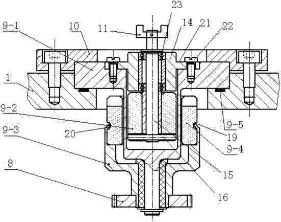
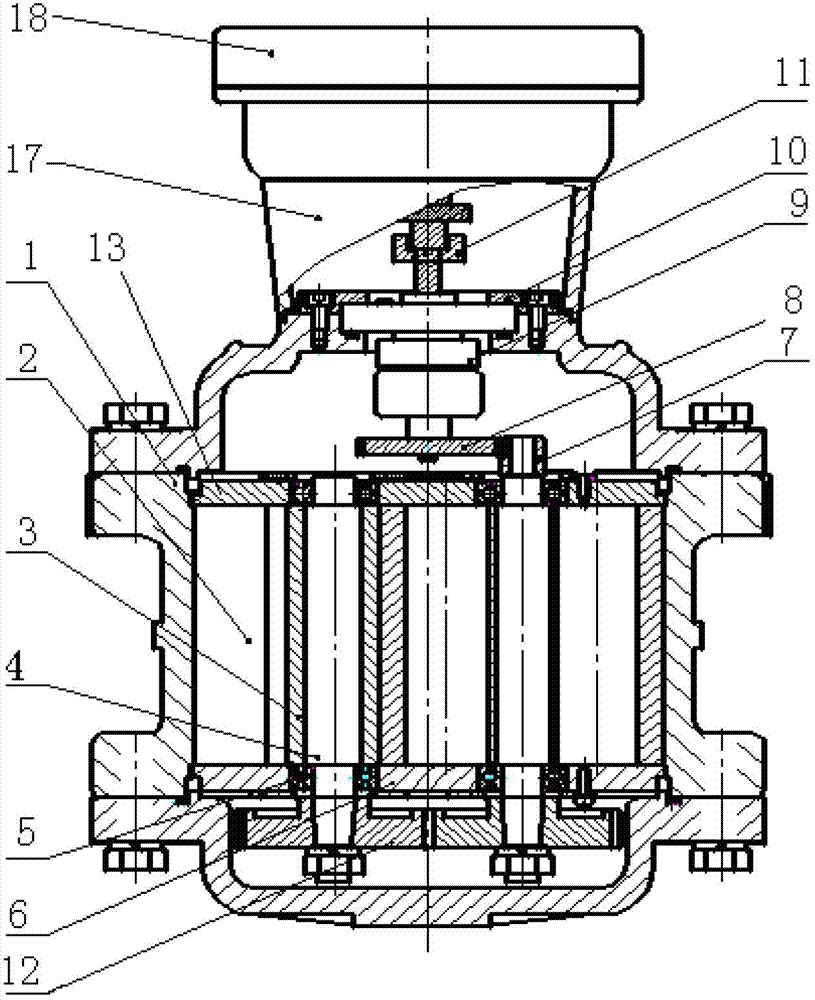
[0023] Referring to the drawings, a waist wheel flow meter includes a housing 1 and a pair of two waist wheel assemblies 2 in the housing 1 that are mutually rolling and rotating. The waist wheel assembly 2 is composed of a waist wheel 3 and a waist wheel shaft 4. The wheel assembly 2 is supported by a rolling bearing 5 and rotates at a high speed, while driving the coaxial transmission gear 7 to rotate. The rolling bearing 5 is fixed on the upper and lower measuring plates 6, 13, and the transmission gear 7 and the sealing coupling 9 are selected. Equipped with gear 8 meshing, sealed coupling 9 includes inner magnetic steel seat 9-1, inner magnetic steel 9-2, outer magnetic steel seat 9-3, outer magnetic steel 9-4 and gasket 9-5. The lower end of the steel base 9-3 is equipped with an optional gear 8. The outer magnet base 9-3 is a cylinder with a stepped through hole in the middle, and the upper end of the cylinder is embedded with an outer magnet 9 that matches the correspond...


PUM


Abstract

The invention discloses a roots flowmeter, which includes a casing, as well as two roots assemblies that are subjected to relative rolling rotation, wherein each of the roots assemblies is composed of a roots and a roots shaft; the roots assemblies are supported on rolling bearings, rotate at high speed, and at the same time drive a coaxial transmission gear to rotate; the rolling bearings are fixed on an upper metering plate and a lower metering plate; the transmission gear is meshed with an optionally matched gear of a sealing coupler; external magnetic steel matched with the corresponding part of a stepped through hole of an external magnetic steel base is embedded in the external magnetic steel base; the middle part of an internal magnetic steel base is matched and mounted inside the external magnetic steel and the external magnetic steel base; a rotating shaft is mounted on the internal magnetic steel base through a rotating shaft sleeve; internal magnetic steel is mounted at the lower end part of the rotating shaft; a transmission claw is mounted at the upper end of the rotating shaft; and the transmission claw is connected with a reducing mechanism. The reducing mechanism performs certain digit-ratio conversion and transmits the result to a counter; and the sealing coupler is tightly pressed on the casing by a metal gland, and is sealed by a seal gasket. The roots flowmeter is reasonable in structural design, is convenient to mount and use, is good in fixing stability, is not easy to loose, and avoids loss of the transmission energy.

Description

Technical field [0001] The present invention relates to a flow meter, in particular to a waist wheel flow meter. Background technique [0002] Waist wheel flowmeter is composed of a shell and a pair of two waist-shaped rotors (waist wheels for short) that are rolling and rotating in the shell. When the measured liquid flows through the measuring chamber, a pressure difference is formed at the inlet and outlet of the flowmeter. The wheel rotates driven by this pressure difference. At the same time, a pair of driving gears fixed on the waist wheel shaft keep the two waist wheels continuously rotating. With the rotation of the waist wheel, the liquid is continuously discharged from the metering chamber through the metering chamber. The amount of liquid flowing through each rotation of the waist wheel is four times the volume of the measuring chamber. The number of rotations of the waist wheel is transmitted to the counter through the sealed coupling and the deceleration mechanism....

Claims


Application Information

Patent Timeline
IPC IPC(8): G01F11/00
Inventor 刘杰甘晓梅彭丹丹高岭孙雪
Owner HEFEI JINGDA INSTR
Why Eureka
Try Eureka