Automatic detection device for touch screen

An automatic detection device, touch screen technology, applied in the direction of measurement device, measurement of electricity, measurement of electric variables, etc., can solve the problem of not being able to fully detect the functional integrity of the touch screen, save detection costs, achieve structural design, and improve detection efficiency. Effect

Active Publication Date: 2013-01-16
TOP TOUCH ELECTRONICS
View PDF9 Cites 3 Cited by
  • Summary
  • Abstract
  • Description
  • Claims
  • Application Information

AI Technical Summary

Problems solved by technology

[0004] Both of the above two touch screens are common touch screens in daily life. Both of them must be tested in the final link of factory production. The detection is often done manually after the touch screen is connected to the drive circuit. However, this This kind of point test often cannot fully detect the functional integrity of the touch screen (for example, the area with normal function is just touched, but the area with abnormal function is not touched), such as whether the infrared emitting tube and infrared receiving tube of the infrared touch screen are Can work normally, or whether the ITO conductive layer of the resistive touch screen is uniform, etc., cannot be completely detected by a simple limited manual touch test

Method used


Image

  • Automatic detection device for touch screen
  • Automatic detection device for touch screen

Examples


Embodiment 1

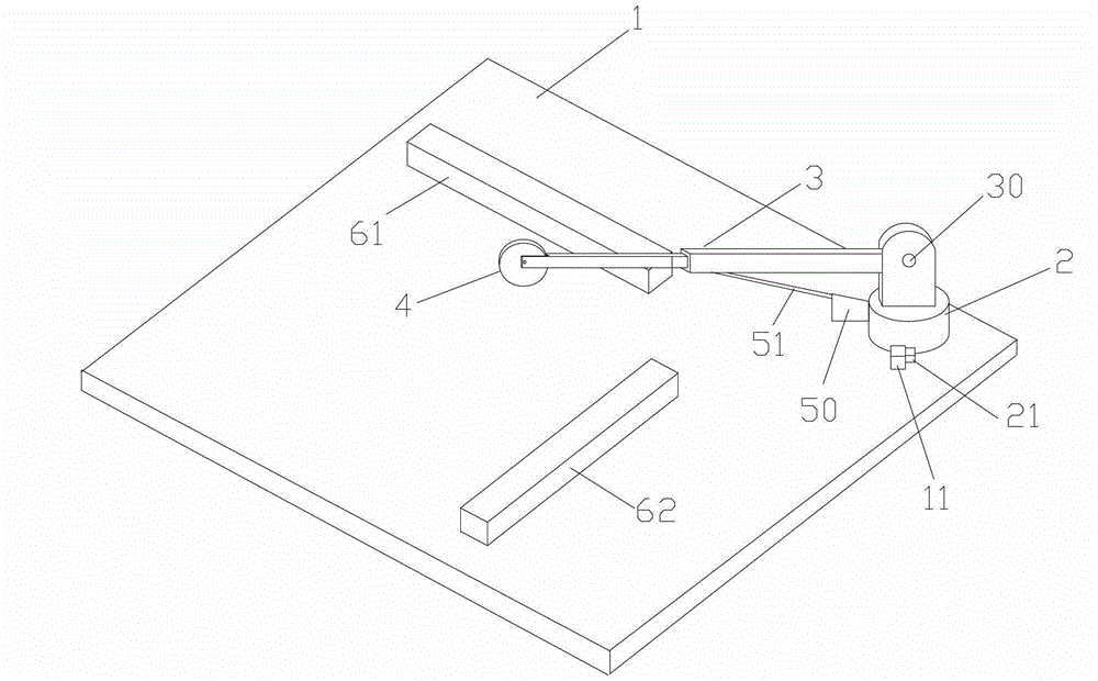
[0023] The embodiment of the present invention provides a touch screen automatic detection device, such as figure 1 As shown, it includes a detection platform 1, a rotating column 2, a telescopic rod 3, and a detection roller 4. The rotating column 2 is rotatably mounted on the detection platform, and one end of the telescopic rod 3 is pivotally connected to the rotating column through a pivot 30 2, and can be rotated in a direction perpendicular to the detection platform 1. The other end of the telescopic rod 3 is rotatably installed with the detection roller 4 and the rotation axis of the detection roller 4 is parallel to the detection platform 1. A driving motor (not shown in the figure) drives to rotate around an axis perpendicular to the detection platform, and the telescopic rod 3 is driven by a second driving motor (not shown in the figure) to move closer to or away from the rotation The direction of the column is telescopic, and the rotating column 2 is also provided wit...

Embodiment 2

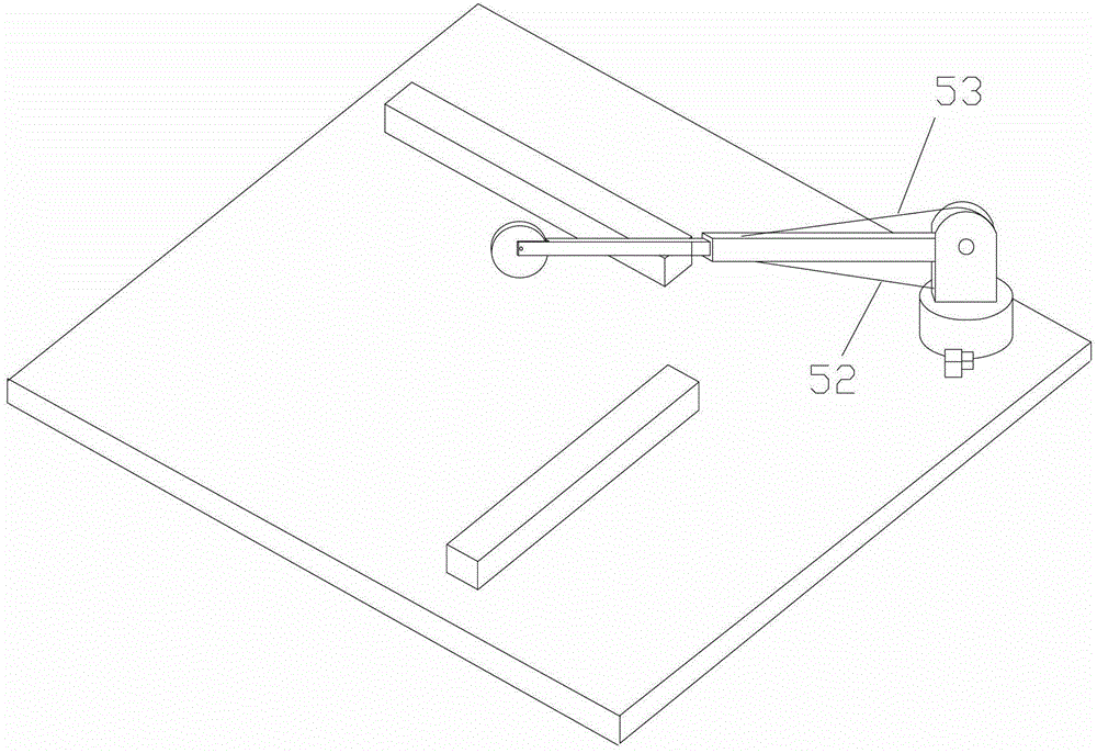
[0037] The difference between the embodiment of the present invention and the first embodiment is the driving device, such as figure 2 As shown, the driving device in the embodiment of the present invention includes a first wire 52, a second wire 53, a first wire winder (not shown in the figure), and a second wire winder (not shown in the figure). One end of the first pull wire 52 is connected to the rear half of the side of the telescopic rod far away from the detection platform, the other end of the first pull wire 52 is wound on the first winder, and one end of the second pull wire 53 is connected to the telescopic rod Approaching the back half of one side of the detection platform, the other end of the second pull wire is wound on the second winder, the first winder and the second winder are respectively located on the rotating column on the upper and lower sides of the pivot . The first winder pulls the telescopic rod from above the pivot (the telescopic rod is pivotally...

Embodiment 3

[0041] The difference between the embodiment of the present invention and the first embodiment above is still in the driving device. The driving device in the embodiment of the present invention is a third driving motor, and the third driving motor is synchronously connected with the pivot to drive the pivot. Rotate.

[0042] In order to realize the synchronous connection between the third drive motor and the pivot, the output shaft of the third drive motor can be coaxially connected with the pivot, and only a side wall of the rotating column needs to be provided for fixing the third drive motor Then, the output shaft of the third drive motor and the pivot shaft are coaxially fixedly connected.

[0043] Of course, the third drive motor can also be synchronously connected through a transmission belt, a transmission chain, or a transmission gear. These synchronous connection modes are known to those skilled in the art, and will not be repeated here.

[0044] It can be understood that ...


PUM


Abstract

The invention discloses an automatic detection device for a touch screen, and belongs to the technical field of touch screen detection equipment. The automatic detection device for the touch screen comprises a detection platform, a rotary vertical column, a telescopic rod and a detection roller. The telescopic rod is pivoted to the rotary vertical column which is mounted on the detection platform, the detection roller is mounted at the front end of the telescopic rod, and after the touch screen is placed on the detection platform, the rotary vertical column can guarantee the roller to transversely and longitudinally detect the touch screen, and the telescopic rod can guarantee the roller to reciprocate along the edge of the touch screen to detect the touch screen. An automatic detection function is realized by means of the simple structural design, and detection efficiency is improved while detection cost is saved.

Description

Technical field [0001] The invention relates to the technical field of detection equipment, in particular to an automatic detection device for a touch screen. Background technique [0002] The infrared touch screen uses the infrared matrix densely distributed in the X and Y directions to detect and locate the user's touch. The infrared touch screen is equipped with a circuit board frame in front of the display. The circuit board arranges infrared emitting tubes and infrared receiving tubes on the four sides of the screen to form a horizontal and vertical cross infrared matrix. When the user touches the screen, the finger will block the horizontal and vertical two infrared rays passing through the position, so the position of the touch point on the screen can be judged. Any touch object can change the infrared ray on the contact to realize the touch screen operation. [0003] The main part of the resistive touch screen is a resistive film screen that fits well with the surface of ...

Claims


Application Information

Patent Timeline
Patent Type & Authority Applications(China)
IPC IPC(8): G01R31/00
Inventor 毛肖林
Owner TOP TOUCH ELECTRONICS
Why Eureka
Try Eureka