Installation structure for capacitor

A technology for mounting structures and capacitors, applied in capacitors, electrical components, etc., can solve problems such as unfavorable capacitor heat dissipation, capacitor shaking, capacitor explosion, etc., and achieve the effects of promoting use, ensuring stability, and protecting capacitors

Inactive Publication Date: 2013-01-16
SUZHOU TANGFENG ELECTRICAL APPLIANCE
View PDF0 Cites 5 Cited by
  • Summary
  • Abstract
  • Description
  • Claims
  • Application Information

AI Technical Summary

Problems solved by technology

One is to use three spring pieces to fix the bottom of the capacitor, so that the capacitor is no longer limited to one type of bracket and can only fix a capacitor with one diameter. However, after a long time of use, the spring pieces will lose their ability to return to their original shape due to plastic deformation. nature, cannot effectively fix the capacitance
The other is to use Ω-shaped fixing strips to fix the capacitor. There is a buckle on the side of the capacitor, and the buckle is fixed on the capacitor bracket through bolts. Although this fixing method achieves a certain degree of stability, its structure is too complicated , and the buckle and the fixing strip itself are relatively narrow, and the bolt is fixed at one point. For a working environment with large shaking or harsh conditions, the capacitor will shake and vibrate, and if the fixing strip and the ring There are many buckles, which is not conducive to the heat dissipation of the capacitor. It is easy to cause the capacitor to explode due to the high temperature and the heat cannot be effectively dissipated. There is a great potential safety hazard.

Method used


Image

  • Installation structure for capacitor
  • Installation structure for capacitor
  • Installation structure for capacitor

Examples


Embodiment Construction

[0015] The present invention is described below in conjunction with accompanying drawing.

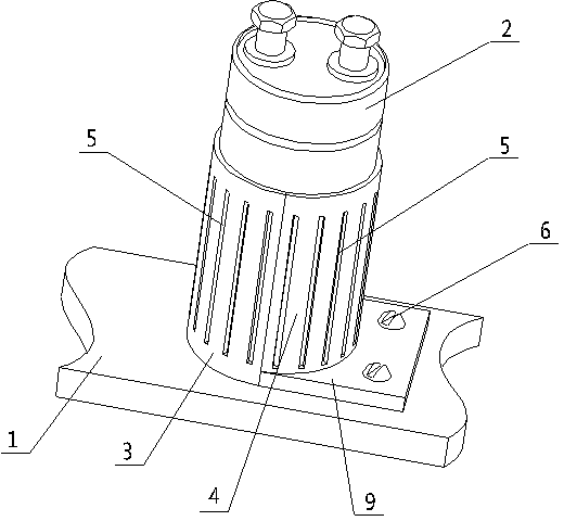
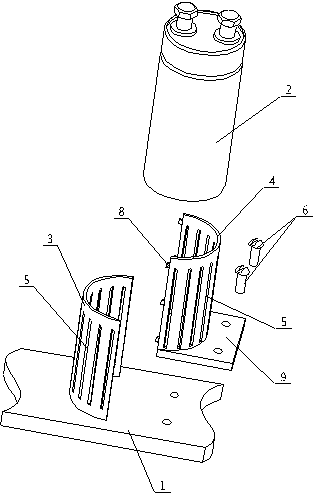
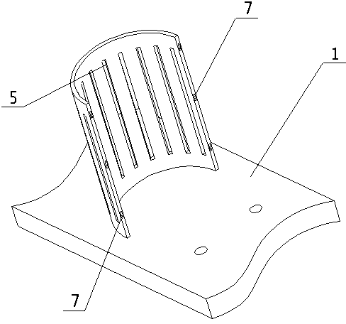
[0016] attached Figure 1-4 It is a capacitor mounting structure according to the present invention, comprising a mounting base plate 1, a capacitor 2, a left fixed plate 3, a right fixed plate 4 and a movable plate 9; the left fixed plate 3 is welded on the mounting base plate 1, and its cross section is Semi-circular, and its inner diameter is the same as the outer diameter of the capacitor 2; the shape of the right fixed plate 4 is consistent with that of the left fixed plate 3, and its openings face each other and cooperate with each other; the height of the left fixed plate 3 and the right fixed plate 4 Both are 3 / 4 times of the height of the capacitor 2; the opening end of the left fixing plate 3 is provided with a fixing groove 7; the opening end of the right fixing plate 4 is provided with a protrusion 8 matched with the fixing groove 7; Movable plate 9 is welded on the bottom ...


PUM


Abstract

The invention discloses an installation structure for a capacitor, which comprises an installation bottom plate, the capacitor, a left fixing plate, a right fixing plate and a movable plate, wherein the left fixing plate is welded on the installation bottom plate; the section of the left fixing plate is semi-annular; the internal diameter of the left fixing plate is the same as the external diameter of the capacitor; the left fixing plate and the right fixing plate have the same appearance, and are provided with opposite openings and matched with each other; the heights of both the left fixing plate and the right fixing plate are as 3 / 4 time as the height of the capacitor; a fixing groove is formed at the opening end of the left fixing plate; a bump matched with the fixing groove is arranged at the opening end of the right fixing plate; the movable plate welded at the bottom of the right fixing plate is located on the right side of the right fixing plate; the movable plate is fixed on the installation bottom plate by screws; and heat dissipation grooves are uniformly formed on the left fixing plate and the right fixing plate. The installation structure can protect the capacitor very well, adapt to different severe working environments and ensure the stability of the capacitor, is simple in structure and convenient to install, and facilitates promotion and using.

Description

technical field [0001] The invention relates to an installation structure, in particular to a structure for installing capacitors in electrical equipment, belonging to the field of electrical equipment accessories. Background technique [0002] For the field of electrical equipment, capacitors are one of the indispensable devices, and how to install and fix capacitors has always been the direction of efforts of those skilled in the art. At present, there are mainly two ways to fix capacitors, one is fixed by screws at the bottom, and the other is fixed by brackets. On the one hand, when fixing the capacitor with screws, it needs to be rotated continuously. If multiple capacitors are installed and fixed at the same time, the gap between the capacitors is very small, and the operation is very inconvenient; on the other hand, when fixing with a bracket, if the diameter of the bracket is slightly larger than The diameter of the capacitor will cause the capacitor to shake in the...

Claims


Application Information

Patent Timeline
IPC IPC(8): H01G2/02H01G2/04
Inventor 唐祥根
Owner SUZHOU TANGFENG ELECTRICAL APPLIANCE
Why Eureka
Try Eureka