
Push-type switch

A push and switch technology, applied in the parts of flip switches/rocker switches, etc., can solve the problems of complex structure of push switches, unstable operation, and no push switches.

Inactive Publication Date: 2013-01-16
浙江松洋电工实业有限公司
View PDF6 Cites 5 Cited by
  • Summary
  • Abstract
  • Description
  • Claims
  • Application Information

AI Technical Summary

Problems solved by technology

[0002] The existing push switch has complex structure and unstable operation, and there is no push switch close to the present invention in the prior art

Method used


Image

  • Push-type switch
  • Push-type switch
  • Push-type switch

Examples


Embodiment Construction

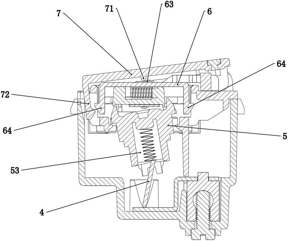
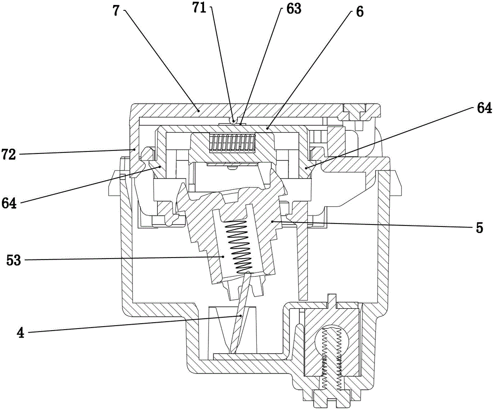
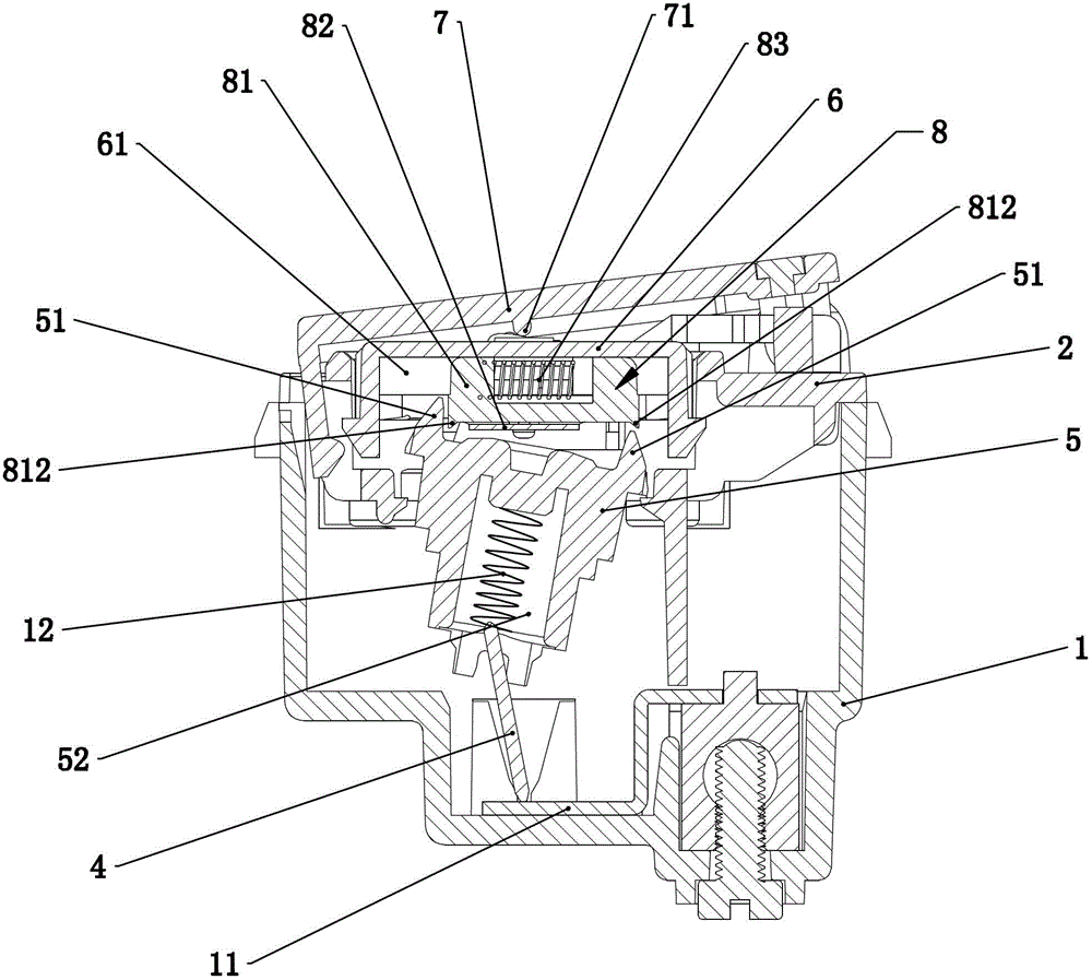
[0019] Such as figure 1 — Figure 10 As shown, a push-type switch includes a base 1, a bracket 2, a static contact 3, a moving contact 4, a swing member 5, a button 6 and an operation panel 7, wherein one end of the operation panel 7 is hinged on the bracket 2, and the bracket 2 is buckled on the base 1, the static contact 3 is fixedly arranged on the base 1, one end of the movable contact 4 is in contact with the conductive sheet 11 of the base 1, and the other end is pressed against the swing member 5 by the movable contact spring 12, The button 6 is movably arranged on the support 2, a return spring 9 is arranged between the button 6 and the support 2, and the button 6 is provided with a sliding mechanism 8 on one side of the swing member 5, and the cooperation of the sliding mechanism 8 and the swing member 5 Realize the left and right swing of the pendulum 5 so as to drive the movable contact 4 to swing left and right and realize the conduction and disconnection with the...


PUM


Abstract

The invention relates to a push-type switch. According the technical scheme of the invention, the push-type switch is characterized by comprising a base, a bracket, a static contact, a dynamic contact, a swinging piece, a button and an operation panel, wherein one end of the operation panel is hinged on the bracket; the bracket is buckled on the base; the static contact is fixedly arranged on the base; one end of the dynamic contact is pressed against a conducting sheet of the base, and the other end of the dynamic contact is pressed against the swinging piece through a dynamic contact spring; the button is movably arranged on the bracket; a reset spring is arranged between the button and the bracket; one side of the button which is positioned on the swinging piece is provided with a slippage mechanism; and leftward and rightward swinging of the swinging piece is realized by matching the slippage mechanism and the swinging piece, so that the dynamic contact is driven to swing leftwards and rightwards, and matching of switch-on and switch-off of the dynamic contact and the static contact is realized. Due to the adoption of the technical scheme disclosed by the invention, the defects existing in the prior art are overcome and a novel push-type switch which has the advantages of simple and reasonable structure and long service life is provided.

Description

technical field [0001] The invention relates to a push switch. Background technique [0002] The existing push switch has complex structure and unstable operation, and there is no push switch close to the present invention in the prior art. Contents of the invention [0003] The purpose of the present invention is to overcome the shortcomings of the prior art and provide a new type of push-type switch with simple structure, reasonable structure and long service life. [0004] In order to achieve the above object, the present invention adopts the following technical solutions: a push-type switch, characterized in that it includes a base, a bracket, a static contact, a moving contact, a swing piece, a button and an operation panel, wherein one end of the operation panel is hinged on On the bracket, the bracket is buckled on the base, the static contact is fixed on the base, one end of the moving contact is in contact with the conductive sheet of the base, and the other end...

Claims


Application Information

Patent Timeline
IPC IPC(8): H01H23/16
Inventor 张红卫
Owner 浙江松洋电工实业有限公司
Learn More