Temporary earthing clamp device

A temporary grounding wire, articulated technology, applied in the direction of electrical connection seat, clamping/spring connection, etc., can solve the problems of low work efficiency and stay, to ensure the reliability of grounding, easy replacement and adjustment, and ensure the convenience of operation. Effect

Active Publication Date: 2013-01-16
ANSHAN POWER SUPPLY COMPANY OF STATE GRID LIAONING ELECTRIC POWER COMPANY +1
View PDF6 Cites 9 Cited by
  • Summary
  • Abstract
  • Description
  • Claims
  • Application Information

AI Technical Summary

Problems solved by technology

With the development of power grid technology, the substation equipment itself is generally equipped with grounding devices (such as grounding knife switch, grounding switch), but the grounding device (such as temporary grounding wire) used for power line power outage operations still stays in the traditional structure. , it needs to be temporarily installed on the ground terminal during operation, the operation is cumbersome and time-consuming, and it needs to be completed with tools, and the work efficiency is low. Therefore, it is urgent to develop a new temporary ground clamp to improve the installation efficiency of the ground wire when the power line is out of power.

Method used


Image

  • Temporary earthing clamp device
  • Temporary earthing clamp device

Examples


Embodiment Construction

[0016] The specific embodiment of the present invention will be further described below in conjunction with accompanying drawing:

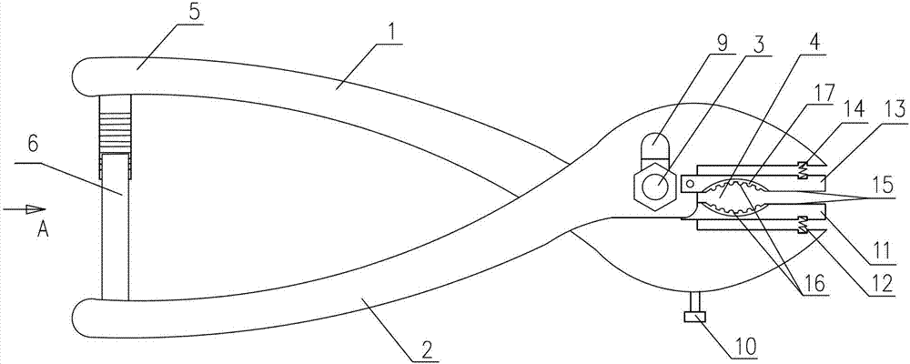
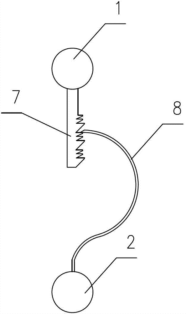
[0017] See figure 1 , figure 2 , is a structural schematic diagram of an embodiment of the temporary grounding clamp device of the present invention, including component one 1, component two 2 and hinge pin 3, component one 1 and component two 2 are hinged together by hinge pin 3, component one 1 and component two 2 correspond One end of the bite is the jaw 4, the other end of the first component 1 and the second component 2 is the handle 5, and the end of the handle 5 is provided with a locking and positioning device 6.

[0018] The locking and positioning device includes locking teeth 7 and elastic curved plates 8. The locking teeth 7 are arranged on component one 1, and the elastic curved plates 8 are arranged on component two 2. Surface sliding realizes the relative position fixing of component one 1 and component two 2 . The hole 9 that c...


PUM


Abstract

The invention relates to the temporary earthing field, in particular to a temporary earthing clamp device which is characterized by comprising a member I, a member II and a hinge pin, wherein the member I and the member II are hinged together through the hinge pin; the corresponding meshed end of the member I and the member II is a jaw, and the other ends of the member I and the member II are handles; a locking positioning device is arranged at the end parts of the handles and comprises a locking tooth on the member I and an elastic curved plate on the member II; and the end part of the elastic curved plate slides along the surface of the locking tooth under the action of an external force so as to realize relative position fixing of the member I and the member II. Compared with the prior art, the temporary earthing clamp device has the advantages that 1, the installation procedures of the earthing terminal of the temporary earthing wire are simplified, so as to ensure operation convenience and reliability of the temporary earthing and improve the installation efficiency of the earthing wire in operation in case of power failure of a power line; 2, the connection requirement between ground studs with different cross sections and a tower material is met; and 3, convenience is brought for replacement and adjustment of the temporary earthing clamp.

Description

technical field [0001] The invention relates to the field of temporary grounding, in particular to a temporary grounding clamp device. Background technique [0002] The function of the ground wire in the power line is a reliable safety measure used to protect the staff from being injured by a sudden power call at the workplace. At the same time, it can also be used to discharge the remaining charge of the disconnected part of the equipment and the only technology to avoid the electric shock of the staff. measure. With the development of power grid technology, the substation equipment itself is generally equipped with grounding devices (such as grounding knife switch, grounding switch), but the grounding device (such as temporary grounding wire) used for power line power outage operations still stays in the traditional structure. , It needs to be temporarily installed on the ground terminal during operation, the operation is cumbersome and time-consuming, and it needs to be ...

Claims


Application Information

Patent Timeline
Patent Type & Authority Applications(China)
IPC IPC(8): H01R11/24H01R4/48
Inventor 孙道军王金朝张连贵刘天东夏岩孙新鑫
Owner ANSHAN POWER SUPPLY COMPANY OF STATE GRID LIAONING ELECTRIC POWER COMPANY
Why Eureka
Try Eureka