A system for eye imaging

An imaging and eye technology, which is used in eye testing equipment, ophthalmoscopes, medical science, etc. It can solve the problem of eliminating ghosts and stray light. The optical structure is complex, it cannot completely eliminate ghosts and stray light, and the utilization rate of light sources is low. problems, to achieve the effect of comfortable examination, easy adaptation of patients, and guaranteed image quality

Active Publication Date: 2014-10-08
SHANGHAI MEDIWORKS PRECISION INSTR CO LTD
View PDF9 Cites 0 Cited by
  • Summary
  • Abstract
  • Description
  • Claims
  • Application Information

AI Technical Summary

Problems solved by technology

[0005] 1. Ghosting and stray light cannot be completely eliminated, and the resulting image quality is still poor
[0006] 2. The illumination light path and the observation light path are independent, and the cost is high
[0007] 3. The optical structure to eliminate ghost and stray light is relatively complex and bulky
[0008] 4. When the annular diaphragm is used, the utilization rate of the light source is low, so the energy consumption is relatively large
[0009] 5. The luminous flux entering the patient's eyes is relatively large, which may easily cause eye discomfort for the patient
[0010] At present, there is no imaging system and method that overcomes the above defects, has higher imaging quality, relatively simple structure, low cost, less energy consumption, and less side effects on patients' eyes.

Method used


Image

  • A system for eye imaging
  • A system for eye imaging
  • A system for eye imaging

Examples


Embodiment Construction

[0036] The specific embodiment of the present invention will be further elaborated below in conjunction with accompanying drawing:

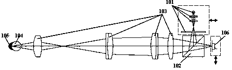
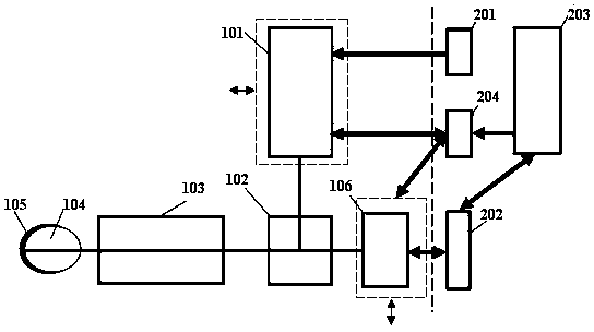
[0037] exist figure 1 In a principle diagram of an embodiment of the present invention, the system consists of a light source module 101, a spectroscopic module 102, a shared optical path module 103, an eye 104, a fundus 105, an image receiver 106; a light source power supply module 201, an image receiver drive module 202, a control It is composed of a processing display module 203 and a motion driving module 204.

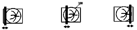
[0038] The light source module 101 moves radially along the upstream illumination light path formed by the light source module 101 and the light splitting module 102; The radial movement of the downstream observation optical path; the movement driving module 204 is respectively connected with the light source module 101 and the image receiver 106 to directly control the movement synchronization of the light source module 101 and the ...


PUM


Abstract

Related to the field of ophthalmic optical instrument, a system and method for eye-imaging, primarily for use in fondues examination, designed to eliminate ghosting when photographing for an eye examination, and to implement high quality imaging. The system comprises a light source module (101), a spectral module (102), a common optical path module (103), an image receiver (106), a light source power supply module (201), an image receiver driver module (202), a control / processing / display module (203), and a motion driver module (204). The motion driver module (204) is connected to and drives simultaneously the motion of the light source module (101) and of the image receiver (106). This allows a light of the light source module (101) to be reflected onto the image receiver (106) for exposure after scanning an eye (104), then to be splicing processed for imaging, displaying, and recording by the subsequent control / processing / display module (203).

Description

technical field [0001] The invention relates to the field of ophthalmic optical instruments, in particular to an eye imaging system and method. Background technique [0002] At present, optical instruments for eye detection or photography generally include an illumination optical path and an observation optical path. The illumination optical path is used to illuminate the eyes of the observed person, and the reflected light is irradiated to the observer's eyes or the observation device through the observation optical path. to observe and photograph the health status of the eyes, including the fundus. [0003] However, due to the complex structure of the patient's eye, the specific physiological tissue conditions are also varied, especially when optical instruments are used for observation and photography, in many cases, excess reflected light from the cornea and the surface of the eye contact lens will form ghost images after passing through the optical instrument, thus Thi...

Claims


Application Information

Patent Timeline
Patent Type & Authority Patents(China)
IPC IPC(8): A61B3/14A61B3/12A61B3/10
CPCA61B3/14A61B3/154A61B3/12
Inventor 严苏峰魏悦陈文光孔昭松
Owner SHANGHAI MEDIWORKS PRECISION INSTR CO LTD
Why Eureka
Try Eureka