Siphon type suction dredge

A dredge suction machine and siphon type technology, applied in the direction of the feeding/discharging device of the settling tank, etc., can solve the problems that the dredge nozzle cannot suck mud smoothly, the mud sucking effect is not good, and the working bridge resistance is large, so as to achieve the purpose of suction Good mud effect, reduced power and energy consumption, and reduced resistance

Inactive Publication Date: 2013-01-23
NANTONG BEICHEN MACHINERY EQUIP MFGCO
View PDF6 Cites 11 Cited by
  • Summary
  • Abstract
  • Description
  • Claims
  • Application Information

AI Technical Summary

Problems solved by technology

The traditional mud scraper is a flat plate structure that is close to the bottom of the pool. The working bridge has great resistance during the movement process, and when the mud scraper scrapes the mud, the sludge is tightly accumulated on the front of the mud scraper, and the mud suction nozzle cannot absorb mud smoothly. The mud suction effect is not good, and maintenance is inconvenient

Method used


Image

  • Siphon type suction dredge
  • Siphon type suction dredge
  • Siphon type suction dredge

Examples


Embodiment Construction

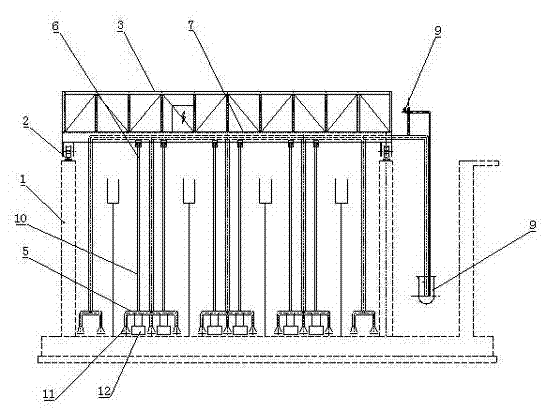
[0011] like figure 1 , 2 , 3, including sewage treatment tank 1, guide rail 2, working bridge 3, end beam 4, horizontal mud suction pipe 5, underwater mud suction pipe 6, water mud discharge pipe 7, water seal cylinder 8, vacuum pumping system 9, Hanger 10, suction nozzle 11, diamond-shaped mud scraper 12.

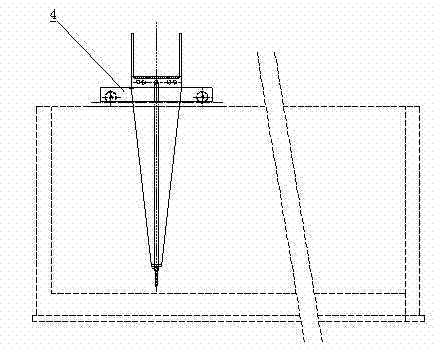
[0012] There are guide rails 2 on both sides of the pool top of the sewage treatment pool 1, and the installation structure between the guide rail 2 and the pool top is as follows: Figure 4 As shown, steel plates 11 are pre-embedded at certain intervals on the top of the pool, and the size of the pre-embedded steel plates 11 is 200*100*12mm. Two groups of bolt connection holes are drilled on the plate 21, the guide rail 2 is placed on the top surface of the pool, and the backing plate 21 is connected with a pressure plate 23 by bolts 22, and the inner end of the pressure plate 23 presses the bottom of the guide rail 2.

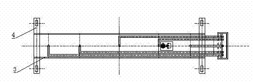
[0013] The working bridge 3 spans the two guide ...


PUM


Abstract

The invention relates to a siphon type suction dredge. The siphon type suction dredge comprises a working bridge, guide rails, a driving device, sludge suction nozzles, underwater sludge suction pipes and overwater sludge discharge pipes, wherein the working bridge stretches across the guide rails; and the driving device is arranged on the working bridge. The innovation is that: the bottom of a pool is provided with a plurality of transverse sludge suction pipes which are connected with the underwater sludge suction pipes and the overwater sludge discharge pipes, the tail ends of the overwater sludge discharge pipes are connected into a water sealing cylinder, and the overwater sludge discharge pipes are also connected with a vacuum-pumping system; and a plurality of sludge suction nozzles are arranged on each transverse sludge suction pipe, and a rhombic scraper is arranged between the adjacent sludge suction nozzles. The working bridge does reciprocating motion along the guide rails; after the vacuum-pumping system is started, sludge enters the transverse sludge suction pipes, the underwater sludge suction pipes and the overwater sludge discharge pipes through the sludge suction nozzles under negative pressure, and then falls into the water sealing cylinder; the sludge is divided toward two sides and is pushed to positions in front of the sludge suction nozzles by utilizing the forward movement of the rhombic scrapers, so that the sludge suction nozzles can suck the sludge conveniently, and the siphon type suction dredge has a good sludge suction effect; and meanwhile, the resistance when the working bridge moves forwards is reduced, so that the power and energy consumption of the driving device can be correspondingly reduced.

Description

technical field [0001] The invention relates to a siphon type dredge machine, in particular to a siphon type dredge machine with small walking resistance and good mud suction effect. Background technique [0002] The siphon suction mud machine is used for advection sedimentation in sewage treatment plants and waterworks. It scrapes the sludge settled at the bottom of the pool to the suction port, sucks the mud while walking, and then discharges the sludge out of the pool to remove and clean the sludge at the bottom of the pool. suffering. The siphon suction dredger consists of a working bridge, a dredging pipe, a dredging pipe, a driving mechanism, an electric control box, guide rails and a submerged dredging pump. The traditional mud scraper is a flat plate structure that is close to the bottom of the pool. The working bridge has great resistance during the movement process, and when the mud scraper scrapes the mud, the sludge is tightly accumulated on the front of the mu...

Claims


Application Information

Patent Timeline
Patent Type & Authority Applications(China)
IPC IPC(8): B01D21/24
Inventor 刘焱忠王满祥
Owner NANTONG BEICHEN MACHINERY EQUIP MFGCO
Why Eureka
Try Eureka