Reversing device for electronic components

A technology of electronic components and reversing devices, which is applied in the direction of conveyor objects, transportation and packaging, etc., to achieve the effect of cost saving and motor protection

Inactive Publication Date: 2013-01-23
FOSHAN BLUE ROCKET ELECTRONICS
View PDF8 Cites 3 Cited by
  • Summary
  • Abstract
  • Description
  • Claims
  • Application Information

AI Technical Summary

Problems solved by technology

In addition, the electronic components are pressed down together with the suction nozzle, and this pressing action may interfere with the mechanical parts below.

Method used


Image

  • Reversing device for electronic components
  • Reversing device for electronic components
  • Reversing device for electronic components

Examples


Embodiment Construction

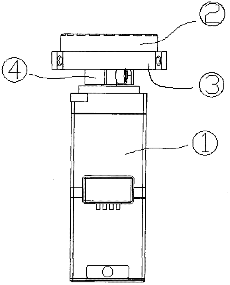
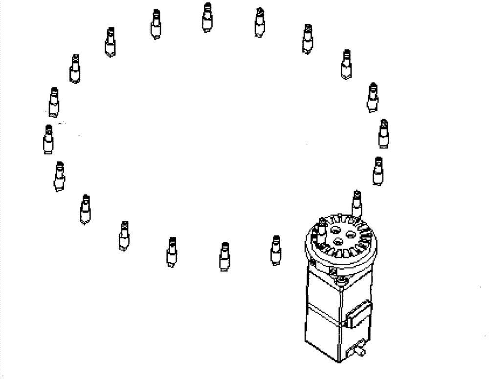
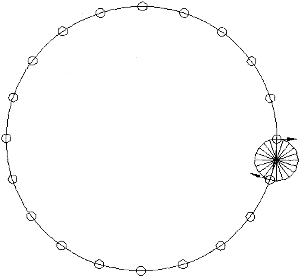
[0028] Such as figure 1 and figure 2 As shown, the electronic component reversing device described according to the present invention includes: a servo motor ①, a small turntable ②, a vacuum plate ③, and a connecting block ④, wherein the servo motor is connected to the small turntable through a connecting block, and can be dragged Turn the small turntable. image 3 As shown, there are several suction nozzles distributed on the large turntable above, the relative positions of the two turntables, and the arrows indicate the direction of the electronic components. Figure 4 As shown, when the electronic components adsorbed on the suction nozzle of the large turntable need to change direction, the suction nozzle releases the electronic components and is taken over by the small turntable below with vacuum. Figure 5 and 6 As shown, after the electronic components are handed over, the small turntable starts to rotate, and the large turntable also starts to rotate after a certai...


PUM


Abstract

The invention provides a high-speed reversing device for electronic components. The reversing device consists of a servo motor, a small turntable, a vacuum plate and a connecting block, wherein the servo motor which controls the small turntable to rotate is connected with the small turntable through the connecting block. By adopting the reversing device, downlink of upper electronic components is not required, and only a proper gap is required to be reserved so that the electronic components can be taken over by the small turntable. Therefore, the cost is saved. Moreover, the reversing device lowers the requirement on reversing time and is favorable to protect a motor.

Description

technical field [0001] The invention relates to an electronic component, and further relates to a commutation device for a light-emitting diode electronic component. Background technique [0002] Generally speaking, the direction of the components provided by the feeding device of electronic components is random, but the follow-up process requires all electronic components to be collected in the same direction, so it is necessary to convert the direction of these electronic components to achieve consistency. [0003] In the prior art, the most common structure is as Figure 12 and Figure 13 Shown: electronic components 5, reversing block 6, connecting rod 7. This is the most commonly used method. The electronic component 5 moves downward under the action of the motor or the cam divider and enters the through hole of the reversing block 6. The through hole is similar in shape to the electronic component. Then the connecting rod 7 below drives the reversing block 6 to rotat...

Claims


Application Information

Patent Timeline
Patent Type & Authority Applications(China)
IPC IPC(8): B65G47/24
Inventor 余辉灿雒继军林琳
Owner FOSHAN BLUE ROCKET ELECTRONICS
Why Eureka
Try Eureka