
Thermal imager and method for resisting strong-light damage

A thermal imaging camera, strong light technology, applied in instruments, image communication, scientific instruments, etc., can solve problems such as loss of target monitoring, loss, equipment paralysis, etc., to avoid permanent damage

Active Publication Date: 2014-06-04
山东神戎电子股份有限公司
View PDF7 Cites 5 Cited by
  • Summary
  • Abstract
  • Description
  • Claims
  • Application Information

AI Technical Summary

Problems solved by technology

The general thermal imager does not have a device to prevent strong light exposure, and only a label with warning words is pasted on the surface. Because these strong light sources have extremely high thermal radiation, it will cause permanent damage to the imaging components and cause the equipment to be paralyzed. Lost monitoring of the target, causing unnecessary losses

Method used


Image

  • Thermal imager and method for resisting strong-light damage
  • Thermal imager and method for resisting strong-light damage

Examples


Embodiment Construction

[0019] Below in conjunction with accompanying drawing, specific embodiment of the present invention is described in further detail:

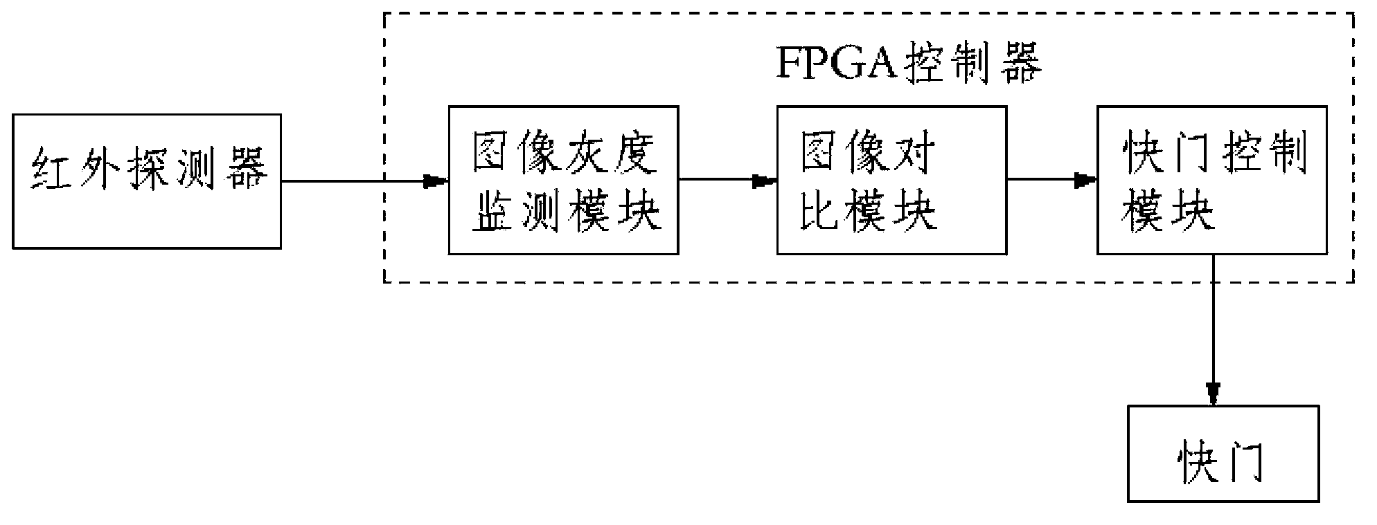
[0020] A kind of anti-glare damage thermal imager of the present invention, comprises infrared lens, shutter and infrared detector, and shutter is connected with the drive motor that drives shutter opening and closing, also comprises FPGA controller, and FPGA controller comprises: image grayscale monitoring module , an image comparison module and a shutter control module.

[0021] The image grayscale monitoring module is connected to the infrared detector signal, and is used to compare the grayscale value in each frame of the image signal output by the infrared detector with the grayscale threshold preset in the image grayscale monitoring module. When the image When a high gray value exceeding the gray threshold appears in a certain area of ​​the signal, the strong light signal is sent out.

[0022] According to the principle of infrared therma...


PUM


Abstract

The invention relates to a thermal imager for resisting strong-light damage, which comprises an infrared camera lens, a shutter and an infrared detector, wherein the shutter is connected with a drive motor capable of driving the shutter to be opened and closed. The thermal image also comprises an FPGA (Field Programmable Gate Array) controller, wherein the FPGA controller comprises an image gray monitor module, am image comparison module and a shutter control module. According to the invention, a method for resisting the strong-light damage comprises a step of controlling a detector to close the shutter on a condition that the FPGA controller detects that multiple frames of images include strong light so as to ensure that the strong light cannot pass through the shutter to damage an imaging element behind the shutter, therefore, the effect of protecting the thermal imager can be achieved.

Description

technical field [0001] The invention relates to an anti-strong light damage thermal imager and a method thereof. Background technique [0002] With the development of thermal imager technology, thermal imagers are more and more widely used, such as forest fire prevention, oil fields, airports, reservoirs, border and coastal defense and other fields. In some application places, because many people do not understand thermal imaging, or are curious, they want to see what will happen when the thermal imager is pointed at a high-temperature object, so they point the thermal imager at the sun, Welding arc, laser and other strong light sources. The general thermal imager does not have a device to prevent strong light exposure, and only a label with warning words is pasted on the surface. Because these strong light sources have extremely high thermal radiation, it will cause permanent damage to the imaging components and cause the equipment to be paralyzed. The monitoring of the t...

Claims


Application Information

Patent Timeline
Patent Type & Authority Patents(China)
IPC IPC(8): G01J5/02G01J5/20H04N5/235
Inventor 王向明王倩倩李鹏徐勤蒲徐玉惠
Owner 山东神戎电子股份有限公司
Learn More