Fuel injection valve
A fuel injection valve and fuel technology, applied in the direction of fuel injection devices, special fuel injection devices, charging systems, etc., can solve the problems of insufficient negative pressure, difficulty in cavitation, different fuel volumes, flow rates, etc., and achieve the promotion of micronization Effect
- Summary
- Abstract
- Description
- Claims
- Application Information
AI Technical Summary
Problems solved by technology
Method used
Image
Examples
Embodiment 1
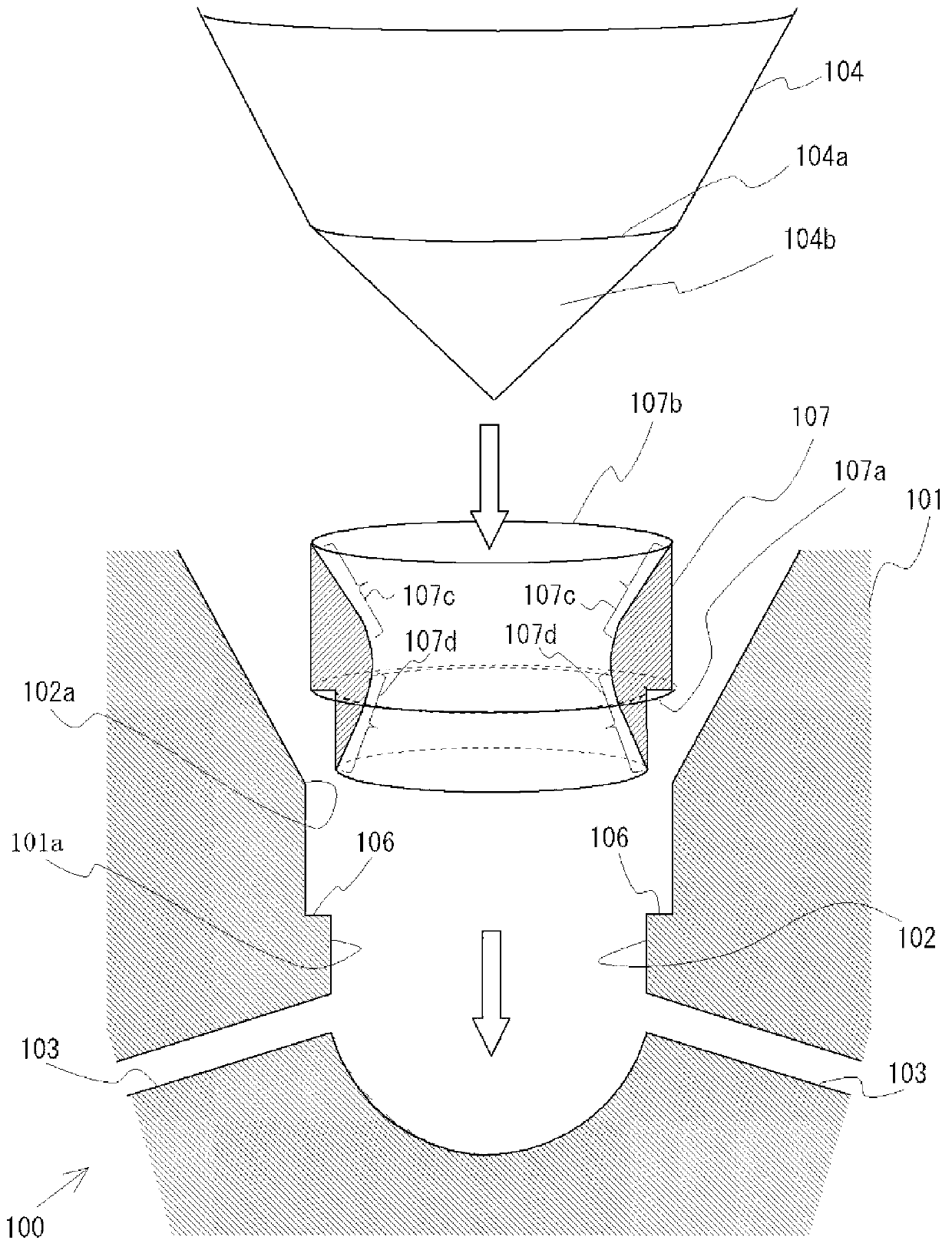
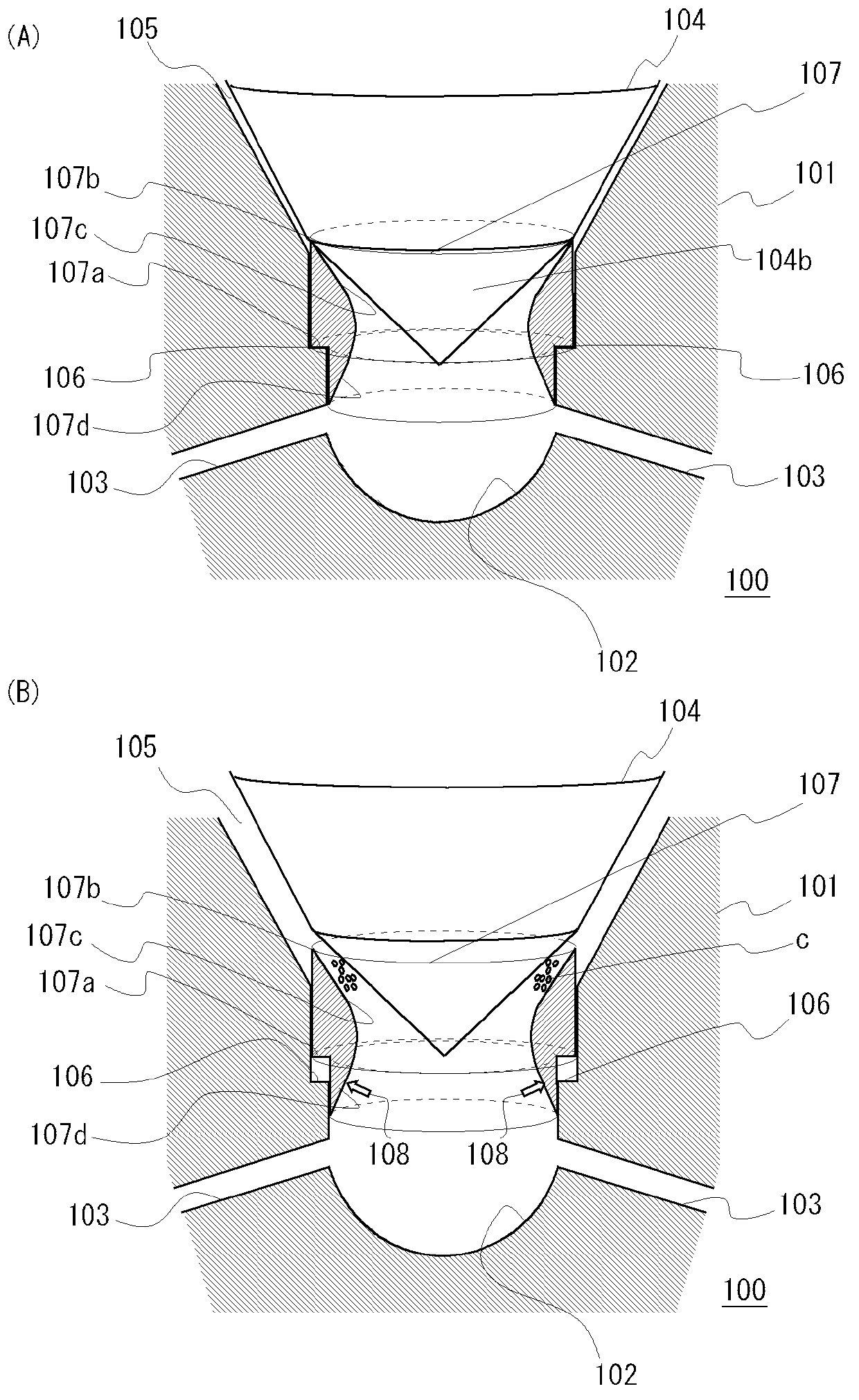
[0029] A fuel injection valve 100 according to Embodiment 1 of the present invention will be described with reference to the drawings. figure 1 It is a schematic diagram showing the front end portion of the fuel injection valve 100 in an exploded state. figure 2 (A) is an explanatory diagram showing the fuel injection valve 100 in a closed state, figure 2 (B) is an explanatory view showing the fuel injection valve 100 in a state where the needle 104 is lifted and the control member 103 is lifted.
[0030] The fuel injection valve 100 includes a nozzle body 101 provided with a bag chamber 102 at a front end thereof and provided with an injection hole 103 opening in the bag chamber 102 . Four injection holes 103 are provided at equal intervals. The fuel injection valve 100 further includes a needle 104 slidably disposed inside the nozzle body 101 , and a fuel inlet leading to the bag chamber 102 is formed between the needle 104 and the nozzle body 101 . Road 105. The valve...
Embodiment 2
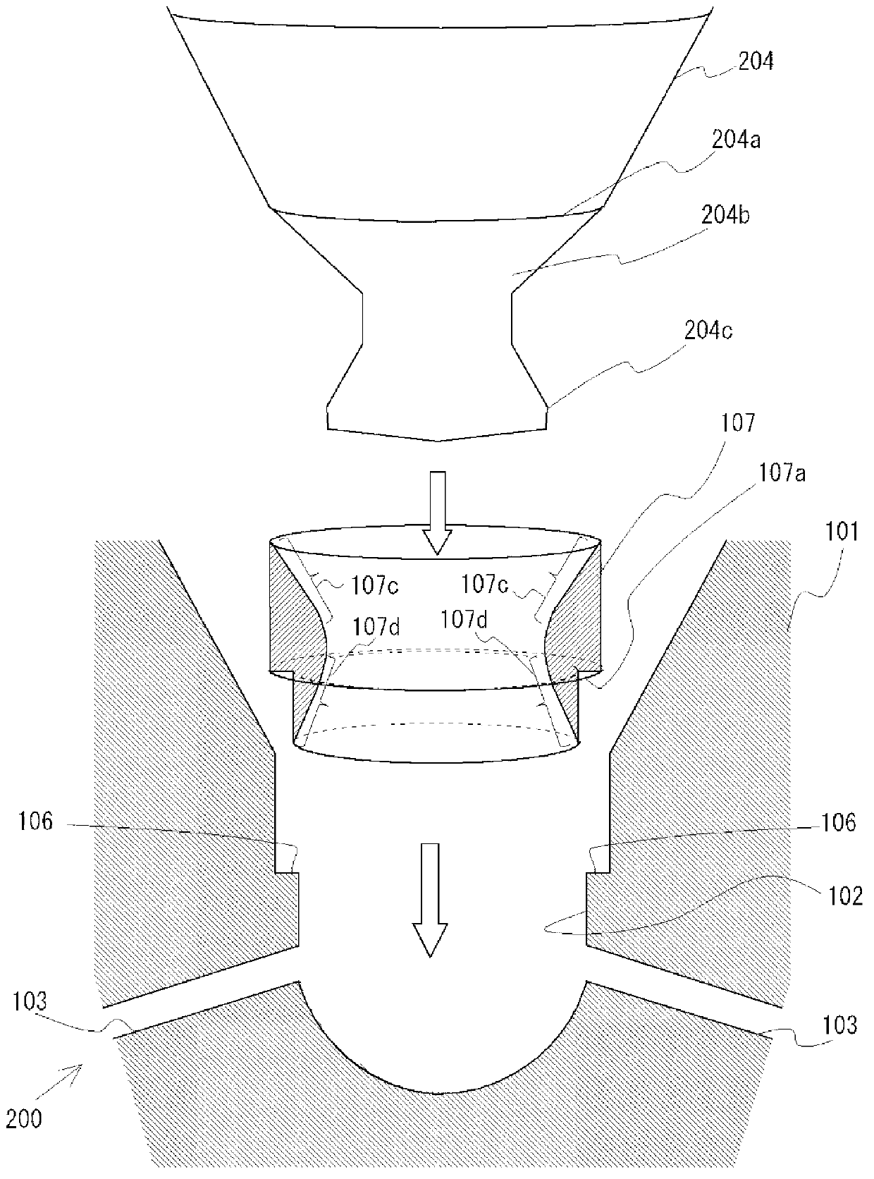
[0041] Next, a fuel injection valve 200 according to Embodiment 2 will be described with reference to the drawings. image 3 It is a schematic diagram showing the front end portion of the fuel injection valve 200 in an exploded state. Figure 4 (A) is an explanatory diagram showing the fuel injection valve 200 in a closed state. Figure 4 (B) is an explanatory diagram showing the fuel injection valve 200 in a low lift state. Figure 4 (C) is an explanatory diagram showing the fuel injection valve 200 in a high lift state.
[0042] The fuel injection valve 200 of the second embodiment differs from the fuel injection valve 100 of the first embodiment in that the fuel injection valve 200 includes a needle 204 instead of the needle 104 . In addition, the fuel injection valve 200 includes the nozzle body 101 and the control member 107 similarly to the fuel injection valve 100 . In the drawings, the same reference numerals are assigned to common components of fuel injection valve...
Embodiment 3
[0054] Next, a fuel injection valve 300 according to Embodiment 3 will be described with reference to the drawings. Figure 5 It is a schematic diagram showing the front end portion of the fuel injection valve 300 in an exploded state. Figure 6 (A) is an explanatory diagram showing the fuel injection valve 300 in a closed state. Figure 6 (B) is an explanatory view showing the fuel injection valve in a low flow rate state. Figure 6 (C) is an explanatory diagram showing the fuel injection valve 300 in a high flow rate state.
[0055] The difference between the fuel injection valve 300 of the third embodiment and the fuel injection valve 100 of the first embodiment is that the fuel injection valve 300 includes a controller 307 instead of the controller 107 . In addition, the fuel injection valve 300 includes the nozzle body 101 and the valve needle 104 similarly to the fuel injection valve 100 . In the drawings, the same reference numerals are assigned to common components ...
PUM
 Abstract
Description
Claims
Application Information
 - R&D
- Intellectual Property
- Life Sciences
- Materials
- Tech Scout
- Unparalleled Data Quality
- Higher Quality Content
- 60% Fewer Hallucinations
Browse by: Latest US Patents, China's latest patents, Technical Efficacy Thesaurus, Application Domain, Technology Topic, Popular Technical Reports.
© 2025 PatSnap. All rights reserved.Legal|Privacy policy|Modern Slavery Act Transparency Statement|Sitemap|About US| Contact US: help@patsnap.com


