Electric surfactant combined repair contaminated soil experimental device
A surfactant and soil-contaminated technology, applied in the field of pollutant treatment in soil, can solve problems such as infiltration and pollution of eluent
- Summary
- Abstract
- Description
- Claims
- Application Information
AI Technical Summary
Problems solved by technology
Method used
Image
Examples
Embodiment 1
[0019] Embodiment 1 The structure of the electrokinetic surfactant combined repairing contaminated soil experimental device of the present invention
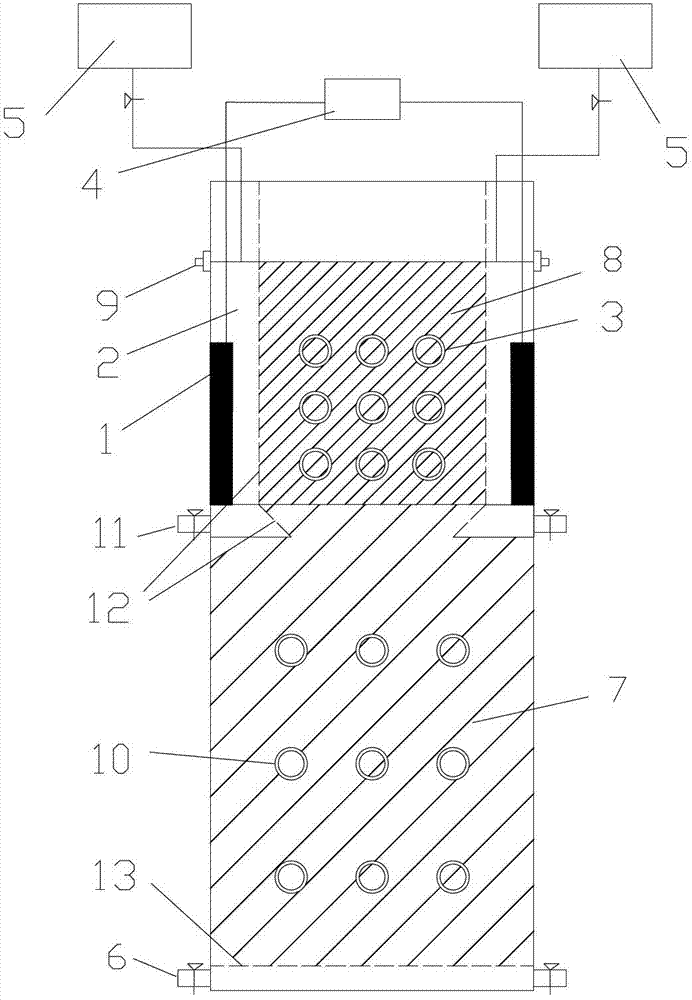
[0020] The structure of the experimental device is as figure 1 shown. figure 1 Among them, 1 is the electrode; 2 is the electrode chamber; 3 is the sampling port of the polluted area; 4 is the DC power supply; 5 is the regulating tank; 6 is the water inlet and outlet; 7 is the uncontaminated soil; 8 is the polluted soil; 10 is the sampling port of the uncontaminated area; 11 is the eluent outlet; 12 is the porous baffle in the electrode chamber; 13 is the porous baffle at the bottom of the reactor.
[0021] The main body of the device of the present invention can be a prismatic tube or a cylindrical tube with an open upper end and a closed bottom end, inside which is a soil chamber, the lower part is filled with uncontaminated soil 7, and the upper part is filled with polluted soil 8 (soil containing polychlorinated biphenyls)....
Embodiment 2
[0024] Example 2 A size of electrokinetic surfactant combined remediation of polluted soil device
[0025] In order to meet the needs of the test, the main body of the device of the present invention is made of plexiglass, which can visually observe the experimental phenomenon. Its height is 25 cm, and the height of the soil chamber in it is 20 cm. There are electrode chambers 2 on the two opposite sides respectively, the width of which is 2.5 cm, and the two electrodes 1 placed in the electrode chambers 2 are plate electrodes of graphite material with a thickness of 0.5 cm.
Embodiment 3
[0026] Embodiment 3 experimental process
[0027] First inject water into the soil chamber through the water inlet and outlet 6 at the bottom of the experimental device, and then put a certain amount of uncontaminated soil 7 into the soil chamber from the top of the main body, continue to enter the water, and at the same time compact the soil layer to drive out the air bubbles, and repeat the layering process. into uncontaminated soil7 until compatible with figure 1 The upper part of the middle eluent outlet 11 is flush, and the uncontaminated area is saturated. Add polluted soil 8 to the top of the polluted area (the lower part of the overflow port 9) in the same way. When the polluted area reaches saturation, water is released from the water inlet and outlet 6 to make the water level drop. At this time, the polluted area and the unpolluted area are both saturation band. The layer of uncontaminated soil 7 flush with the eluent outlet 11 can be considered as a transitional b...
PUM
| Property | Measurement | Unit |
|---|---|---|
| Electric field strength | aaaaa | aaaaa |
| Concentration | aaaaa | aaaaa |
Abstract
Description
Claims
Application Information
 - R&D
- Intellectual Property
- Life Sciences
- Materials
- Tech Scout
- Unparalleled Data Quality
- Higher Quality Content
- 60% Fewer Hallucinations
Browse by: Latest US Patents, China's latest patents, Technical Efficacy Thesaurus, Application Domain, Technology Topic, Popular Technical Reports.
© 2025 PatSnap. All rights reserved.Legal|Privacy policy|Modern Slavery Act Transparency Statement|Sitemap|About US| Contact US: help@patsnap.com


