
Support structure for load measurement sensor

A technology for measuring sensors and sensors, which is applied in the direction of measuring devices, weighing, instruments, etc., and can solve the problem of increasing the height of car seats

Inactive Publication Date: 2013-01-30
TS TECH CO LTD
View PDF5 Cites 2 Cited by
  • Summary
  • Abstract
  • Description
  • Claims
  • Application Information

AI Technical Summary

Problems solved by technology

In recent years, in order to improve the ride performance and design performance of passengers, a technology to reduce the height of the vehicle seat has been expected. The height of 130 is relatively high, so there is a disadvantage that the height of the car seat becomes higher

Method used


Image

  • Support structure for load measurement sensor
  • Support structure for load measurement sensor
  • Support structure for load measurement sensor

Examples


Embodiment Construction

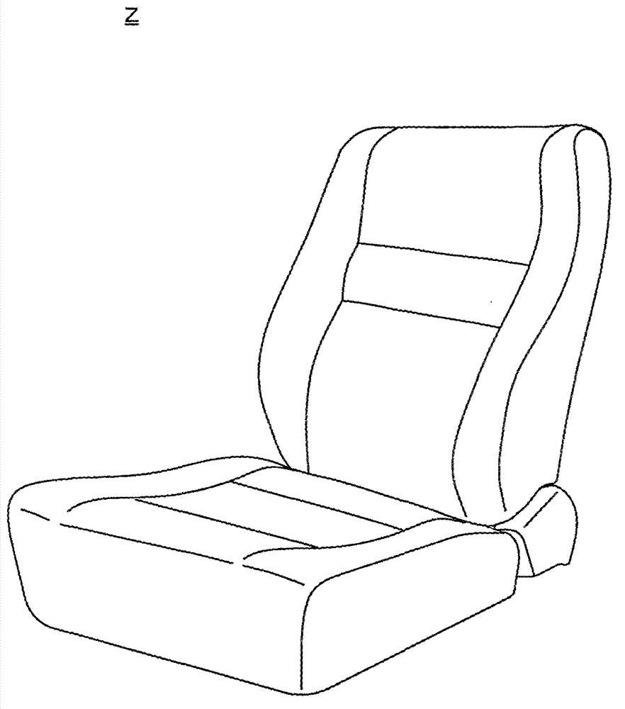
[0109] Below, refer to Figure 1 to Figure 28 The first embodiment (this embodiment) according to the present invention will be described. Here, the load measuring sensor of this embodiment measures the load applied to the vehicle seat Z. In the following description, a support structure for supporting the load measuring sensor in a predetermined posture will be described. Specifies the component.

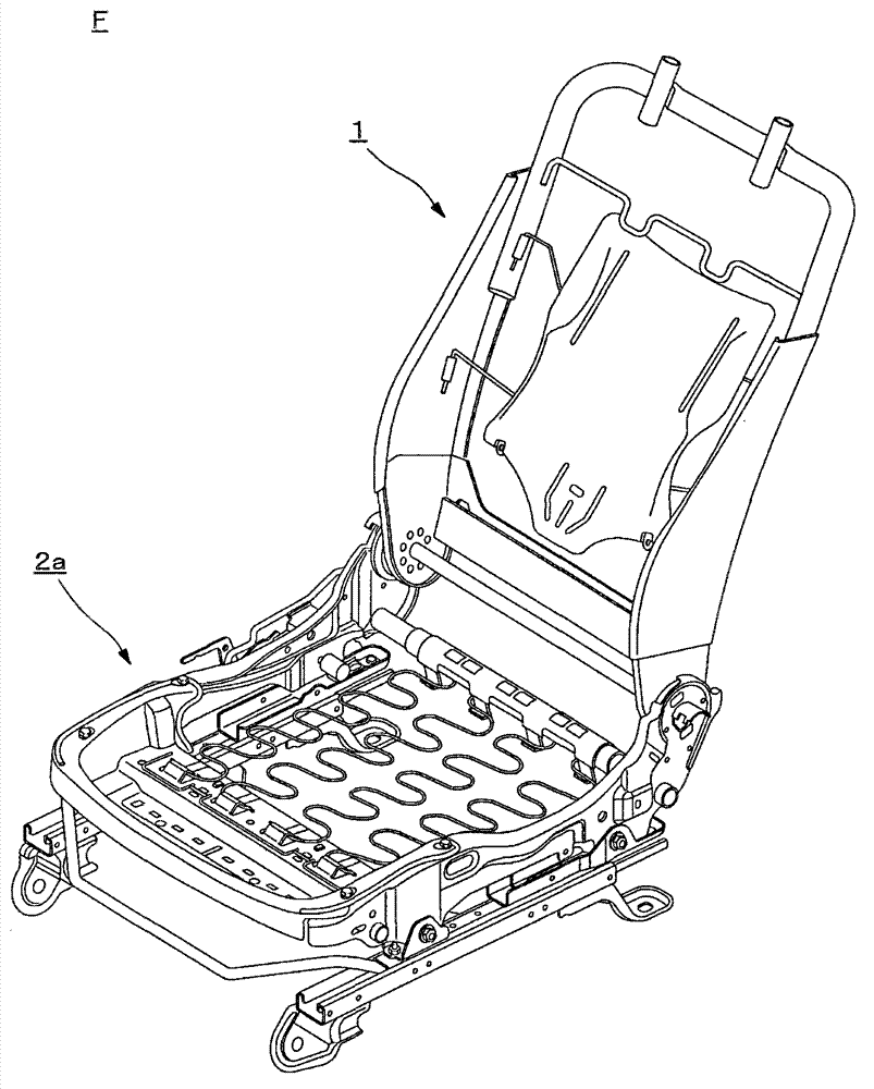
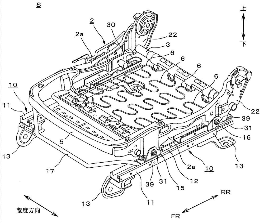
[0110] figure 1 It is a perspective view of a car seat. figure 2 is an oblique view of the seat frame. image 3 is a perspective view showing the seat assembly. Figure 4 is an expanded view of the seat assembly. Figure 5 The diagram showing the supporting structure of the load measuring sensor is a cross-sectional view of the surrounding area of ​​the load measuring sensor. Image 6 and Figure 7 It is a perspective view showing a side frame, Image 6 is the inside surface representing the side frame, Figure 7 is the outer surface of the side frame. Figure 8 It is a...


PUM


Abstract

Provided is a support structure for a load measurement sensor having sufficient durability without adding a large load to a portion transmitting a load to the load measurement sensor. In a support structure for a load measurement sensor (30) which supports the load measurement sensor (30), including a sensor body (32) detecting a load generated from a seat (Z) having a seat frame (1) and an extension shaft portion (31) extending from the sensor body (32), by means of attachment brackets (15, 16) in the state where the extension shaft portion (31) follows the horizontal direction, the support structure includes a load input portion (42) which comes into contact with the sensor body (32) and inputs a load to the sensor body (32), the sensor body (32) includes a load receiving surface (37a) which comes into contact with the load input portion (42) and receives the load, and the load input portion (42) is formed so as to be movable in the axial direction of the extension shaft portion (31) with respect to the load receiving surface (37a).

Description

technical field [0001] The present invention relates to a support structure of a load measurement sensor, and particularly relates to a support structure of a load measurement sensor in which an extension portion extending from a sensor main body is supported in a state of being positioned lateral to the sensor main body. Background technique [0002] For the purpose of improving the safety of passengers and the comfort of seating, technologies have been proposed to control the operation of peripheral equipment of vehicle seats in accordance with the weight of a seated passenger. [0003] In this technique, in general, in order to detect the weight of the occupant, a load measuring sensor is provided below the vehicle seat on which the occupant is seated. [0004] The installation position of the load measuring sensor is generally installed under the vehicle seat, for example, between the slide rail provided to make the vehicle seat slide in the front-rear direction and the ...

Claims


Application Information

Patent Timeline
IPC IPC(8): B60N2/44B60N2/90
CPCG01G19/4142B60R2021/01516B60N2/002
Inventor 小泽英俊本田亘
Owner TS TECH CO LTD
Learn More