Tire-punctured pushing device for electric vehicles

A technology for electric vehicles and flat tires, which is applied in the direction of vehicle control devices, vehicle maintenance, shunting equipment, etc., can solve the problems of increasing the use cost of electric vehicles, limited load capacity, and laborious electric vehicles, so as to reduce the use cost, simple structure, Portable effect

Inactive Publication Date: 2013-01-30
张培生
View PDF6 Cites 8 Cited by
  • Summary
  • Abstract
  • Description
  • Claims
  • Application Information

AI Technical Summary

Problems solved by technology

Because the vehicle body of the electric vehicle is heavier, and it is more difficult for the tire to rotate due to lack of air, it is very laborious to artificially promote the electric vehicle without air; in addition, on the existing electric vehicle, the load capacity of its inner and outer tires is limited, if The tires are pushed without air, and the inner and outer tires cannot withstand long-term walking
It has been calculated that if the tires on ordinary electric vehicles are forced to push for 500 meters under no circumstances, they will be scrapped due to serious damage, which increases the cost of using electric vehicles.

Method used


Image

  • Tire-punctured pushing device for electric vehicles
  • Tire-punctured pushing device for electric vehicles
  • Tire-punctured pushing device for electric vehicles

Examples


Embodiment 1

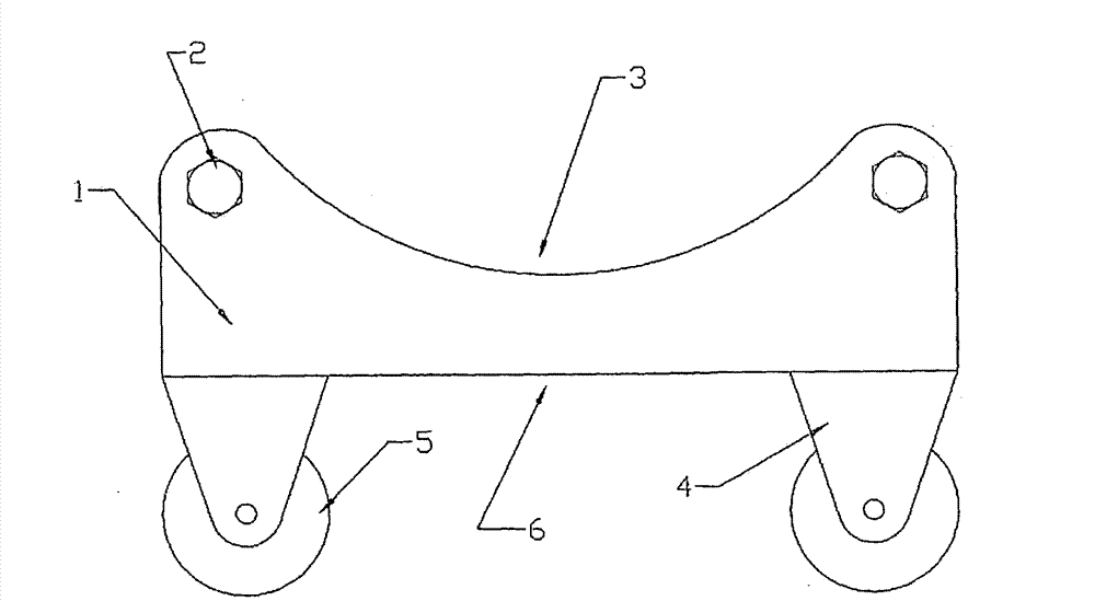
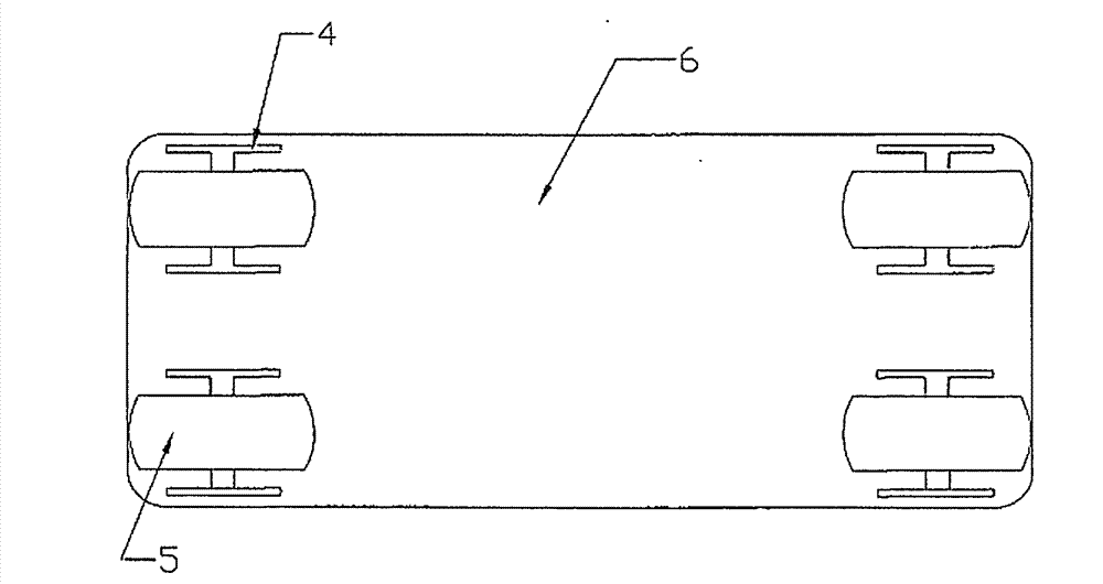
[0022] Such as figure 1 , 2 As shown in , 3, a tire blowout pushing device for an electric vehicle includes a base plate 6, the base plate 6 is rectangular, and pulleys 5 are provided at the concave apexes thereof, and the pulleys 5 are fixedly connected to the base plate 6 through the pulley seat 4 .

[0023] The bottom plate 6 is provided with a clamping device for clamping on the wheel of the electric vehicle. Under the action of the clamping device, the pushing device and the tire of the electric vehicle have better connection firmness during the pushing process.

[0024] The base plate 6 is provided with a support piece 1, and the support piece 1 is located at both side edges in the length direction of the base plate 6. The base plate 6 and the support piece 1 can be formed by bending a whole plate, and are also connected together by welding. The supporting piece 1 generally consists of two pieces, which protrude toward the direction facing away from the pulley 5 , and ...

Embodiment 2

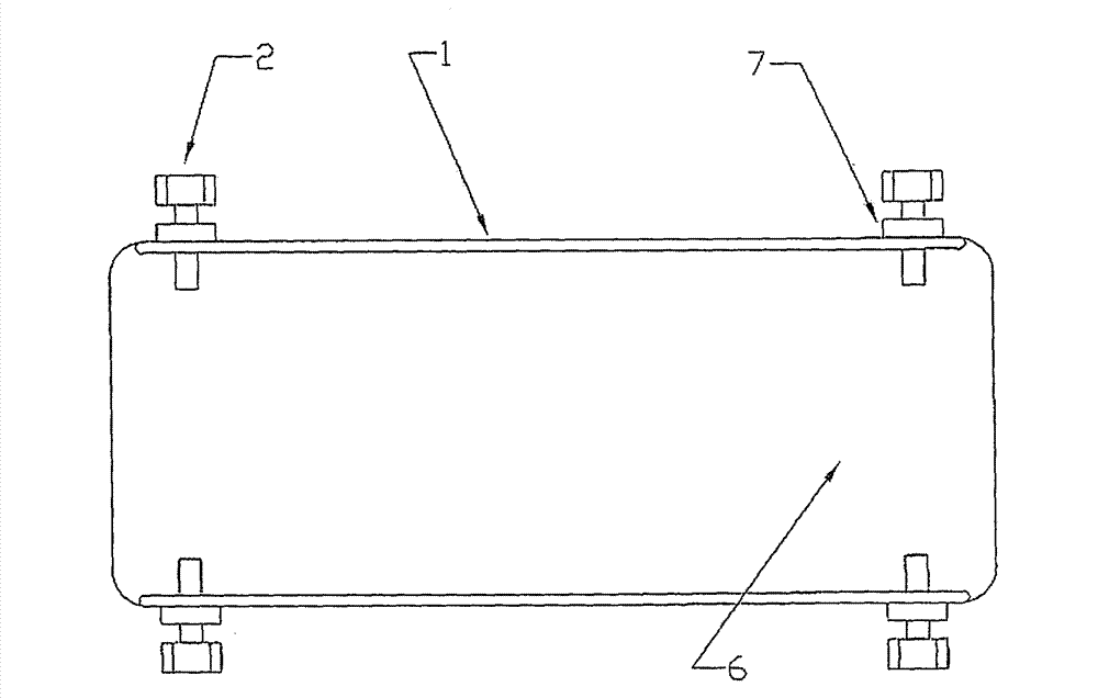
[0028] Such as Figure 4 , 5 As shown, the main structure of pushing the electric vehicle tire blowout is substantially the same as that described in Embodiment 1, except for the specific structure of the clamping device. In this embodiment, the clamping device is an arc-shaped groove formed between the bottom plate 6 and the two support pieces 1 , the arc of the arc-shaped groove coincides with the arc of the wheel of the electric vehicle.

[0029] The support piece 1 is rectangular and has no gaps on it. An arc-shaped piece 8 can be welded between the two support pieces 1, and the bottom of the arc-shaped piece 8 can be in contact with the bottom plate 6, or there is a gap between them, which will be determined according to the actual use . An arc-shaped groove for accommodating the wheel of the electric vehicle can be formed between the two support pieces 1 and the arc-shaped piece 8. When the wheel of the electric vehicle is placed in the arc-shaped groove, the wheel pr...


PUM


Abstract

The invention discloses a tire-punctured pushing device for electric vehicles, which comprises a baseplate, wherein a pulley is arranged on the baseplate, and the baseplate is provided with a clamping-fixing device for being clamped at wheels of an electric vehicle. The pushing device disclosed by the invention has the beneficial effects that when a tire of an electric vehicle is punctured, the punctured tire can be placed on the pushing device disclosed by the invention, and in the process of manually pushing the electric vehicle, an operation that the punctured tire is contacted with the ground to slide is not required, thereby effectively protecting the faulted tire and reducing the application cost of the electric vehicle; because the device is provided with the pulley, an effect of labor saving is achieved in the process of pushing; and in addition, the device disclosed by the invention is simple and lightweight in structure, and easy to carry.

Description

technical field [0001] The invention relates to a protection device for an electric vehicle, in particular to an electric vehicle puncture pushing device for protecting the tire when the electric vehicle needs to be pushed after the tire is blown out. Background technique [0002] Electric vehicles can provide convenience for people's travel, but if the electric vehicle has a tire blowout on the way, it needs to be artificially pushed forward. Because the vehicle body of the electric vehicle is heavier, and it is more difficult for the tire to rotate due to lack of air, it is very laborious to artificially promote the electric vehicle without air; in addition, on the existing electric vehicle, the load capacity of its inner and outer tires is limited, if The tires are promoted without air, and the inner and outer tires cannot withstand long-term walking. It has been estimated that if the tires on ordinary electric vehicles are forced to push for 500 meters under no circumst...

Claims


Application Information

Patent Timeline
Patent Type & Authority Applications(China)
IPC IPC(8): B60S13/02
Inventor 张培生
Owner 张培生
Why Eureka
Try Eureka