
Electromagnet coil tap type charging and degaussing lifting electromagnet

A technology of electromagnet coils and lifting electromagnets, which is applied in the field of lifting electromagnets

Active Publication Date: 2014-10-01
BAOSHAN IRON & STEEL CO LTD
View PDF6 Cites 0 Cited by
  • Summary
  • Abstract
  • Description
  • Claims
  • Application Information

AI Technical Summary

Problems solved by technology

In short, while the lifting electromagnet plays an important role in the lifting and moving of large steel parts, it also brings out many disadvantages.

Method used


Image

  • Electromagnet coil tap type charging and degaussing lifting electromagnet
  • Electromagnet coil tap type charging and degaussing lifting electromagnet
  • Electromagnet coil tap type charging and degaussing lifting electromagnet

Examples


Embodiment Construction

[0015] The present invention will be further described below in conjunction with the accompanying drawings and specific embodiments.

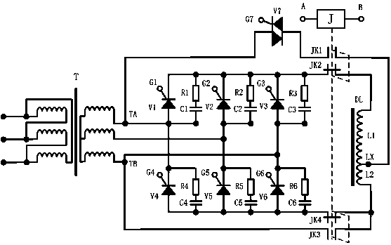
[0016] see image 3 , an electromagnet coil tap type charging and degaussing lifting electromagnet, including one-way thyristor V1-V6 and thyristor bypass protection R1+C1, R2+C2, R3+C3, R4+C4, R5+ The three-phase fully-controlled bridge rectifier circuit composed of C5, R6+C6, and the three-phase transformer T, the output of the three-phase transformer T is connected to the three-phase fully-controlled bridge rectifier circuit, and the output of the three-phase fully-controlled bridge rectifier circuit is connected to the electromagnet coil DL, which is a well-known technique.

[0017] Described electromagnet also comprises contactor J, bidirectional thyristor V7, and contactor J has two pairs of normally open and normally closed contacts; The upper and lower ends are respectively connected with two pairs of normally closed contacts JK2 and ...


PUM


Abstract

The invention discloses an electromagnet coil tap type magnetizing and demagnetizing lifting electromagnet. The lifting electromagnet comprises a three-phase full-control-bridge rectification circuit composed of unidirectional silicon controlled rectifiers V1-V6 and silicon controlled rectifier bypass protections, a three-phase transformer T, a contactor J and a bidirectional silicon controlled rectifier V7, wherein the contactor has two pairs of normally-open contacts and normally-closed contacts; the upper and lower ends of a space between the output end of the three-phase rectification circuit and an electromagnet coil DL are respectively connected with the two pairs of the normally-closed contacts controlled by a controller; the electromagnet coil is divided into an upper coil L1 and a lower coil L2, and two end points of one normally-open contact JK3 are connected with the outer end point of the lower coil and the output point TB of the transformer respectively; the electromagnet coil tap LX is connected with another normally-open contact JK1, the normally-open contact is connected with the bidirectional silicon controlled rectifier V7, and the bidirectional silicon controlled rectifier is connected with the other output point TA of the transformer; and the trigger ends G1-G6 of the unidirectional silicon controlled rectifiers V1-V6 and the trigger end G7 of the bidirectional silicon controlled rectifier V7 are controlled by the controller, and the end points of the contactor are controlled by the controller.

Description

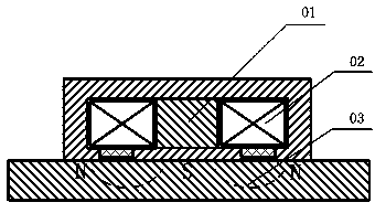
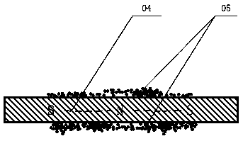
technical field [0001] The invention relates to a lifting electromagnet, in particular to a lifting electromagnet with dual functions of charging and demagnetizing. Background technique [0002] When it comes to plate-shaped steel or larger machine parts and processing parts that need to be moved and lifted, lifting electromagnets will be given priority; the fast and efficient lifting electromagnets have been widely used in equipment manufacturing, logistics and warehousing ; It is especially used in the finished product process movement and product lifting in the iron and steel industry. Since the electromagnet adopts DC power supply, the electromagnet includes the electromagnet core 1 and the excitation coil 2. The electromagnet generates a strong unidirectional magnetic field (magnetic field line 3) and then "penetrates" the attracted object (steel) to form a closed magnetic circuit. See figure 1 , so the electromagnet has also magnetized the steel while absorbing th...

Claims


Application Information

Patent Timeline
Patent Type & Authority Patents(China)
IPC IPC(8): B66C1/08H01F7/06H01F13/00
Inventor 孔利明丁海绍卢江海
Owner BAOSHAN IRON & STEEL CO LTD
Learn More