
Indirectly driven food processor

A food processing machine, an indirect technology, applied in the field of food processing, can solve the problems of shaft hole and cutter shaft wear, high parts processing requirements, unfavorable container cleaning, etc., achieve vibration and noise mitigation, low processing accuracy requirements, and improve magnetic transmission efficiency effect

Active Publication Date: 2013-10-09
JOYOUNG CO LTD
View PDF4 Cites 0 Cited by
  • Summary
  • Abstract
  • Description
  • Claims
  • Application Information

AI Technical Summary

Problems solved by technology

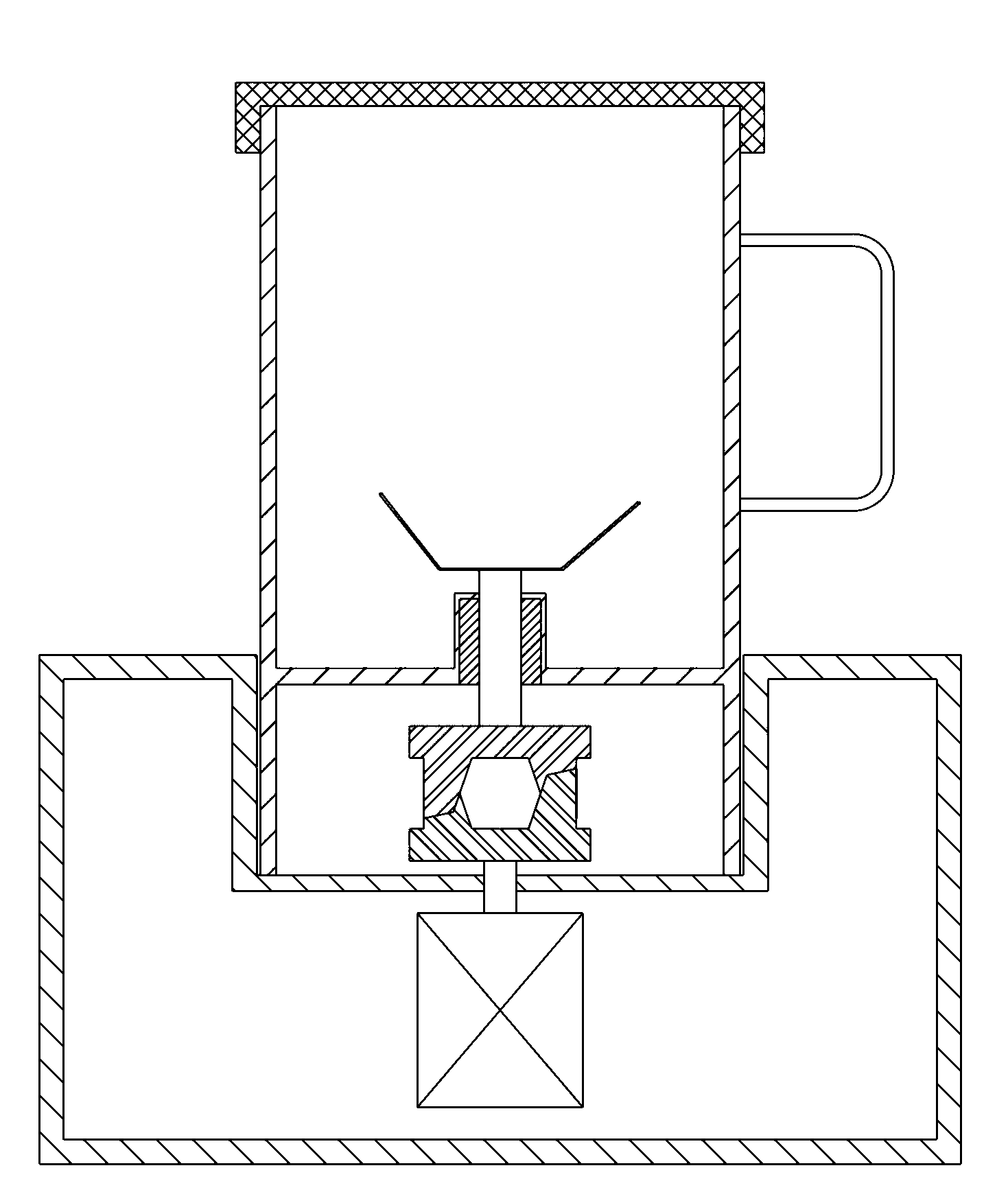
[0005] 1. The active coupling and the driven coupling mesh with each other, and there must be mutual wear, which affects the normal use of the food processor, and the mutual wear of the couplings will produce debris, the debris Risk of swarf entering the container and mixing with the process material
[0006] 2. The driving coupling and the driven coupling are meshed with each other for transmission, which requires high coaxiality of the motor power output shaft and the cutter shaft, and high requirements for the processing of parts, which increases the manufacturing cost; and the said The driving coupling is more prone to wear and has a shorter life when it is eccentric to the driven coupling
[0008] 4. The container is spaced between the driven coupling and the crushing cutter, and the container is provided with a shaft hole for the cutter shaft to pass through. Since the cutter shaft rotates at a high speed relative to the shaft hole, causing The shaft hole and the cutter shaft are worn, and the shaft hole will leak water, which will cause the food processor to be unusable in serious cases
[0009] 5. The crushing tool and the driven coupling are fixed through the cutter shaft, the crushing tool cannot be taken out, which is not conducive to the cleaning of the container, and the crushing tool cannot be taken out, and there is a problem of being damaged when cleaning the container. risk of cuts
[0010] 6. The crushing cutter and the driven coupling are fixed through the cutter shaft, and the crushing cutter is fixed in the axial direction and the radial direction in the container. When processing materials, the materials will be stuck between the crushing cutter and the The crushing cutter is stuck between the containers, and the motor will be blocked. In severe cases, the motor will be burned out, and even the food processor will catch fire.

Method used


Image

  • Indirectly driven food processor
  • Indirectly driven food processor
  • Indirectly driven food processor

Examples


Embodiment 1

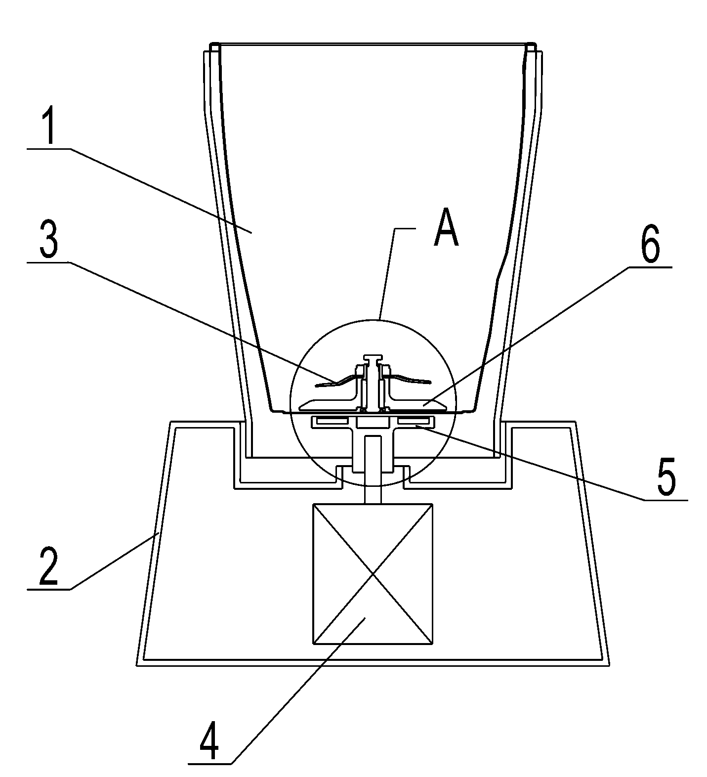
[0047] As the first embodiment of the food processing machine of the present invention, as figure 2 As shown, the food processing machine includes a container 1 , a machine base 2 , a crushing tool 3 , a motor 4 , a driving coupling 5 and a driven coupling 6 . The container 1 is arranged on the base 2, the crushing tool 3 is connected with the driven coupling 6, the motor 4 is vertically arranged in the base 2, and the power output of the motor 4 is A shaft protrudes from the upper end surface of the base 2, and the active coupling 5 is connected with the power output shaft of the motor 4.

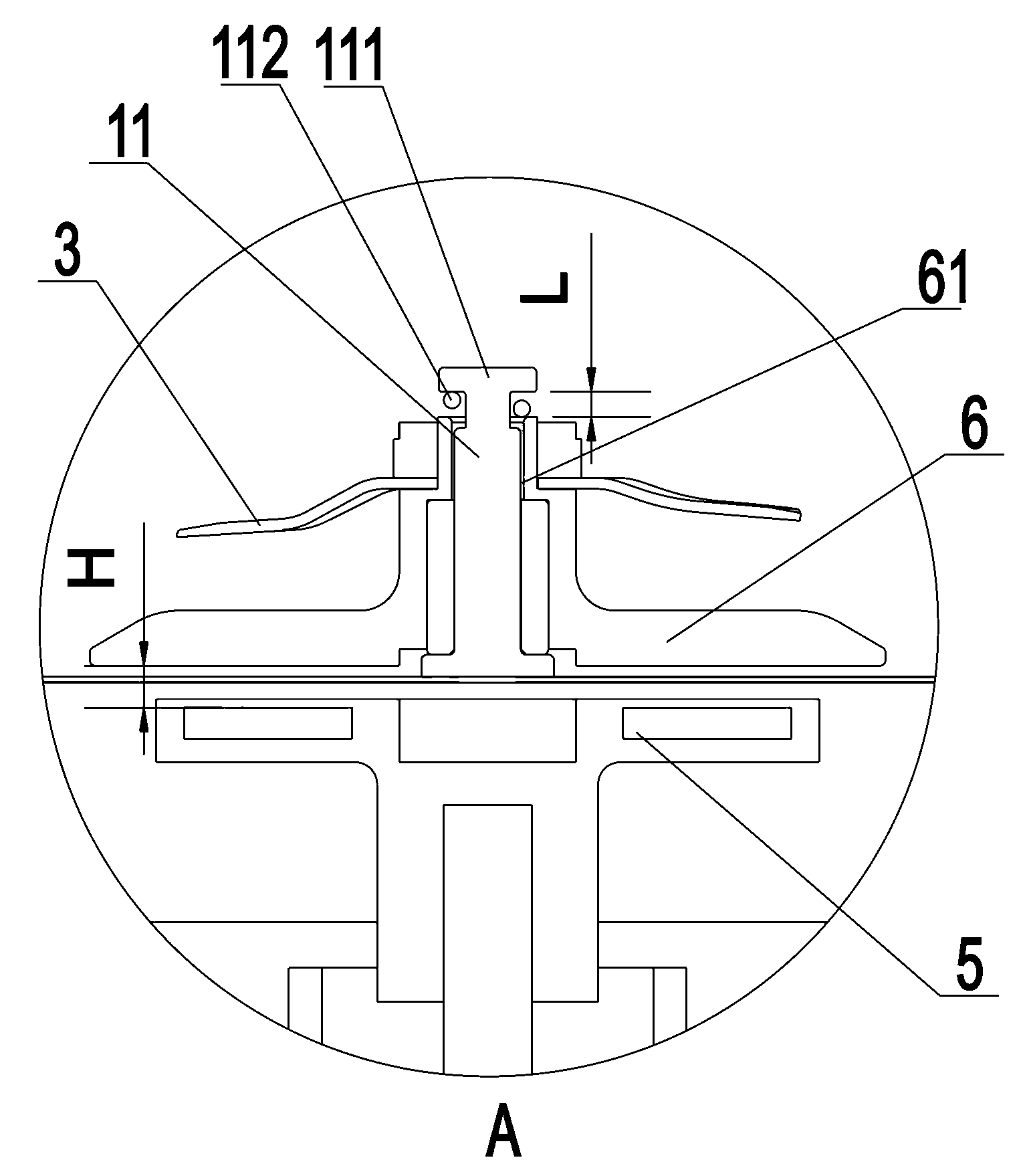
[0048] Such as image 3 As shown, the driven coupling 6 and the crushing tool 3 are integrally arranged in the container 1, the container 1 is provided with a positioning shaft 11, and the driven coupling 6 is provided with a shaft hole 61 , the positioning shaft 11 passes through the shaft hole 61, so that the driven coupling 6 and the crushing tool 3 rotate around the shaft hole 61, a...

Embodiment 2

[0057] As the second embodiment of the food processor of the present invention, as Figure 6 As shown, the difference from the first embodiment is that the container 1 does not include the positioning shaft 11 . The bottom end of the container 1 protrudes inward to form a protrusion 12, and the driven coupling 6 is provided with a recess 64 formed inward, and the protrusion 12 is inserted into the recess 64, so that the driven coupling 6 rotates around said protrusion 12.

[0058] The depression 64 is also provided with a locking groove 641, and the protrusion 12 is also provided with a buckle 121, and the buckle 121 is snapped into the locking groove 641, so that the driven coupling 6 is on the shaft. In addition, the locking groove 641 and the buckle 121 have a floating space, so that the driven coupling 6 is floating in the axial direction. Optionally, the buckle 121 may also be a snap spring. The container 1 is also provided with an elastic member 122, the elastic membe...

Embodiment 4

[0063] As the fourth embodiment of the food processing machine of the present invention, as Figure 8 As shown, the difference from the first embodiment is that the driving coupling 5 and the driven coupling 6 are sleeved together.

[0064] Such as Figure 9 As shown, the bottom end of the container 1 protrudes inward to form a protrusion 12 , and the driven coupling 6 is a metal cylinder and sleeved on the protrusion 12 .

[0065] The active coupling 5 includes a permanent magnet 51 and a cylindrical housing 53, the permanent magnet 51 is embedded in the cylindrical housing 53, the number of the permanent magnets 51 is four, and the plurality of permanent magnets 51 have north and south poles Arranged in sequence with the south magnetic pole, so that the active coupling 5 has a radial magnetic field. Preferably, the active coupling 5 is in a bottomless cylindrical shape, and optionally, the active coupling 5 is in a bottomed cylindrical shape.

[0066] The working gap betw...


PUM


Abstract

The invention discloses an indirectly driven food processor, which comprises a container, a crushing cutter arranged in the container, a motor, a base internally provided with the motor, a driving shaft coupling arranged on a power output shaft of the motor, and a driven shaft coupling connected with the crushing cutter. The indirectly driven food processor is characterized in that: the driving shaft coupling and the driven shaft coupling are in non-contact connection. The driven shaft coupling can be rotatablely arranged in the container and is arranged in a floating mode relative to the container. The driving shaft coupling is made of magnet and the driven shaft coupling is made of metal. The driving shaft coupling and the driven shaft coupling are in non-contact transmission, which caneffectively solve the problem of abrasion between the driving shaft coupling and the driven shaft coupling; the container needs no cutter shaft hole, and sealing to thoroughly solve the problem of container water leakage; vibration and noise can be effectively relieved; the driven shaft coupling is arranged in a floating mode, which can effectively solve the problem of cutter blockage; and the driven shaft coupling and the crushing cutter are dismountable so that the container can be cleaned conveniently.

Description

technical field [0001] The invention relates to the field of food processing, in particular to a non-contact transmission food processing machine. Background technique [0002] A commonly used food processing machine is usually composed of a container and a machine base, the container is connected to the machine base, a crushing tool is arranged in the container, and a motor is arranged in the machine base. The power output shaft of the motor is provided with a driving coupling, and the crushing cutter is connected with a driven coupling. The motor transmits power to the pulverizing tool through the driving coupling and the driven coupling, and drives the pulverizing tool to cut and pulverize. [0003] Such as figure 1 As shown, the existing couplings usually transmit power by means of intermeshing, such as couplings made of plastic or metal. Usually, the motor drives the active coupling, the active coupling meshes with the driven coupling, and the driven coupling is conn...

Claims


Application Information

Patent Timeline
Patent Type & Authority Patents(China)
IPC IPC(8): A47J43/046A47J43/07
CPCA47J43/0465
Inventor 王旭宁王俊陈芳
Owner JOYOUNG CO LTD
Learn More