
Insert molding product

A technology for molded products and resin molding, which is applied to the components of pumping devices for elastic fluids, non-variable displacement pumps, driving pumps, etc., and can solve the use limitations of insert molded products, the complexity of resin molded products, and the increase in manufacturing costs. big problem

Inactive Publication Date: 2013-01-30
KAWAMOTO SEISAKUSHO KK
View PDF7 Cites 2 Cited by
  • Summary
  • Abstract
  • Description
  • Claims
  • Application Information

AI Technical Summary

Problems solved by technology

However, insert molded products only reduce the cost required for disposal, and their strength is inferior to inserts, so there is a concern that they cannot be used in fixed mechanisms
[0019] Such insert molded products may be limited in use, and additional fixing mechanisms are required
Therefore, the insert molded product may complicate the resin molded product and increase the manufacturing cost
In addition, there are cases where it cannot be used when airtightness is required for insert parts

Method used


Image

  • Insert molding product
  • Insert molding product
  • Insert molding product

Examples


Embodiment Construction

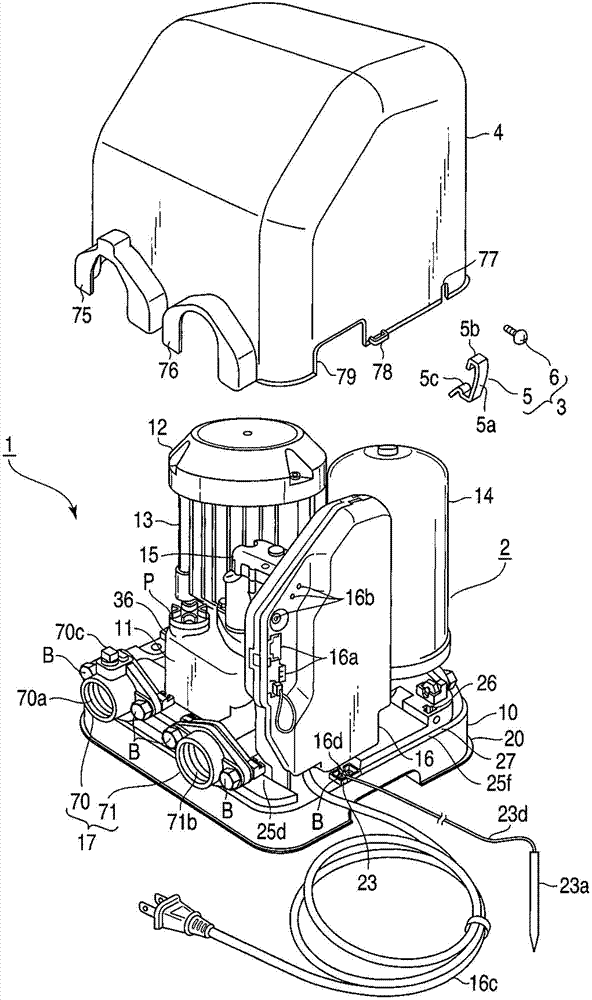
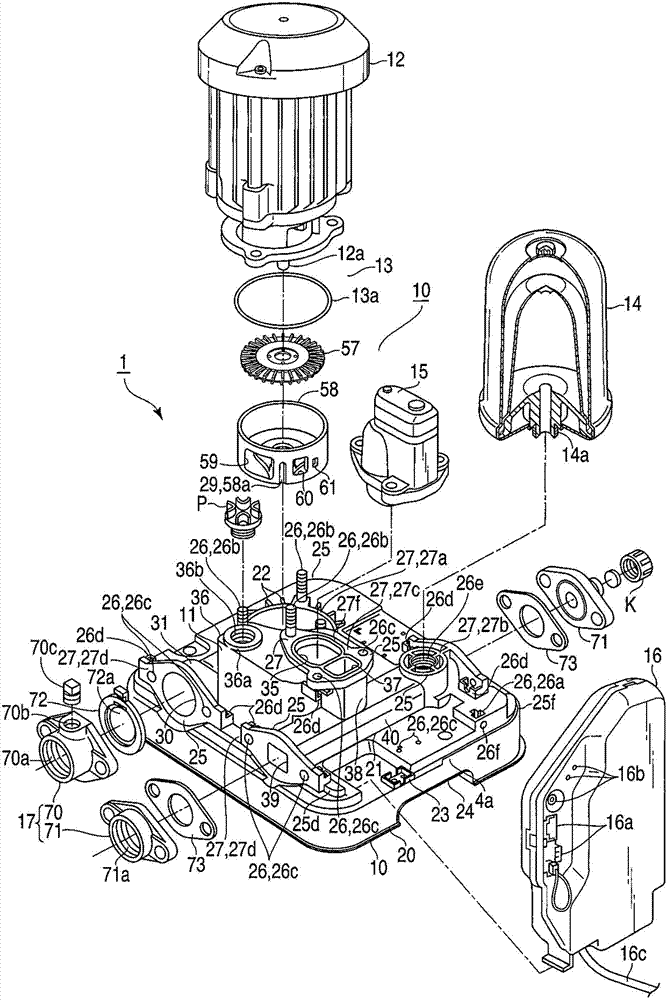
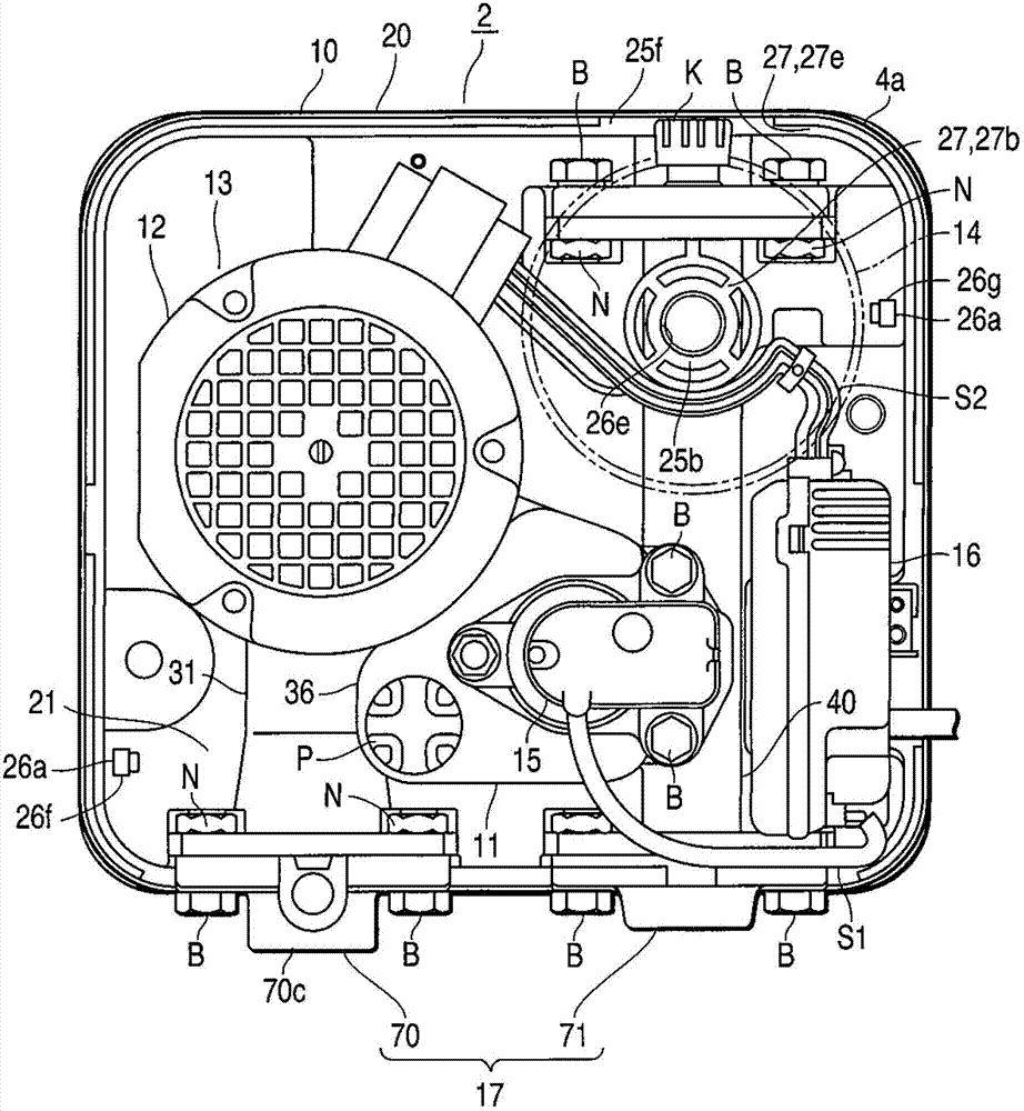
[0040] figure 1 It is a perspective view which shows the structure of the water supply apparatus 1 which concerns on one Embodiment of this invention. figure 2 It is an exploded perspective view showing the configuration of the main body 2 of the same water supply device 1 . image 3 It is a top view showing the structure of the main body part 2 . Figure 4 It is a bottom view showing the structure of the main body part 2 . Figure 5 It is a perspective view which shows the structure of the base part 10 used for the main body part 2. As shown in FIG. Figure 6 It is a plan view showing the structure of the base part 10 . Figure 7 It is a bottom view showing the structure of the base portion 10 . Figure 8It is a cross-sectional view showing the flow path portion 21 of the base portion 10 . In addition, in Figure 1-8 Among them, B represents the bolt, F and F1 represent the flow of water, K represents the cap, P represents the piston, S represents the screw, S1 and S2 ...


PUM


Abstract

A main body (2) of a waterworks (1) comprises an all-in-one base portion (10) made of a resin material, a self-absorption portion (11) which is provided with a self-absorption chamber (36) formed inside theself-absorption portion and used to perform self-absorption, and a self-absorption chamber cover (42) of an opening of the closed self-absorption chamber (36). A pump (13) with a motor (12) is disposed on thebase portion (10). The base (10) comprises a base main body (20) and a flow path portion (21) formed all in one.The flow path portion (21) comprises an absorption flow path portion (31) with a suction inlet (30), a pump housing (34) of a pump (13), the self-absorption chamber (36) of the self-absorption portion (11), and a communicating portion (38) of an opening portion (37), and a discharging flow path portion (40) with two outlets (39) and connected with the communicating portion (38).

Description

[0001] This application is a divisional application of an invention application with an application date of April 24, 2009, an application number of 200910137361.X, and an invention title of "water supply device and embedded molded product". technical field [0002] The present invention relates to a water supply device in which components are arranged on the same base, and an insert molded product in which an insert is inserted into a resin member. Background technique [0003] Conventionally, in order to perform high-efficiency pump operation according to the load from water supply sources such as wells and tanks, there is known a water supply device in which a control device such as an inverter is combined with a pump to which a motor is connected (connected). [0004] As such a water supply device, for example, a water supply device configured by mounting components such as a pump and a control device on a base made of metal or resin, and covering each component with a co...

Claims


Application Information

Patent Timeline
IPC IPC(8): F04D29/00F04D9/02
Inventor 丰田耕司玉川充加藤康志新垣彰平
Owner KAWAMOTO SEISAKUSHO KK
Learn More