
Sealing device

A sealing ring and housing technology, applied in the direction of engine sealing, engine components, mechanical equipment, etc., can solve the problems of sealing failure, destroying the continuity of oil film, reducing sealing effect, etc., and achieving the effect of preventing sealing failure.

Inactive Publication Date: 2013-01-30
SUZHOU DONGLI MACHINERY
View PDF0 Cites 0 Cited by
  • Summary
  • Abstract
  • Description
  • Claims
  • Application Information

AI Technical Summary

Problems solved by technology

[0004] However, the medium in the shell will contain solid impurities. When the sealing device operates at high speed, these solid impurities will inevitably enter the sealing end face and destroy the continuity of the oil film; at the same time, the solid impurities will also inhibit the spring and affect The floating of the compensation ring seat is reduced, the sealing effect is reduced, and the seal fails

Method used


Image

  • Sealing device
  • Sealing device

Examples


Embodiment Construction

[0013] The present invention is described below in conjunction with accompanying drawing.

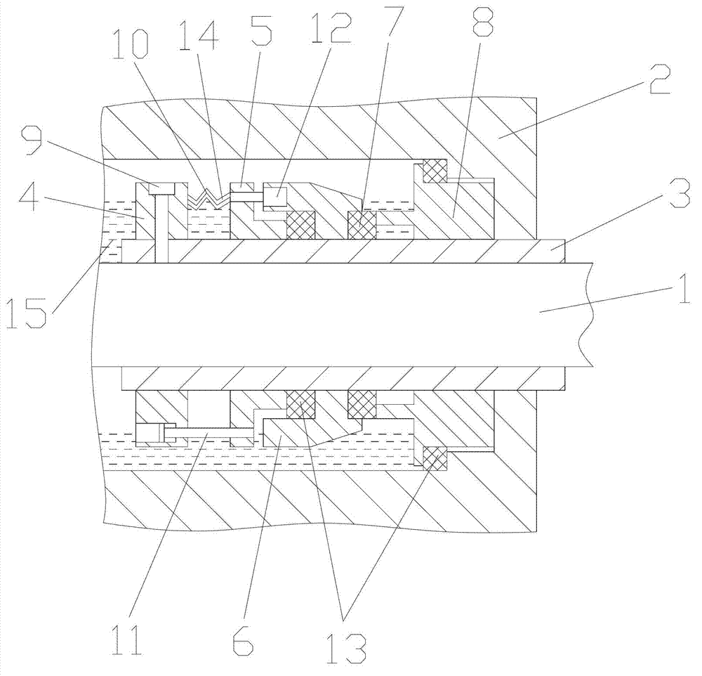
[0014] as attached figure 2 The shown sealing device of the present invention includes a power input shaft 1, a casing 2, a shaft sleeve 3, a spring seat 4, a push ring 5, a compensation ring seat 6, a moving ring 7, a static ring 8, a tightening ring Screw 9, spring 10, transmission screw 11, transmission pin 12 and sealing ring 13, the power input shaft 1 passes through the shell 2, and is arranged in the shell 2, the power input shaft 1 is covered with a shaft sleeve 3, and the shaft sleeve 3 is in turn There are spring seat 4, push ring 5, compensation ring seat 6, moving ring 7 and static ring 8, the static ring 8 is close to the end of the housing 1, the spring seat 4 is fixed on the shaft sleeve 3 through the set screw 9, A spring 10 and a transmission screw 11 are provided between the spring seat 4 and the push ring 5, the push ring 5 and the compensating ring seat 6 are conne...


PUM


Abstract

The invention discloses a sealing device which comprises a power input shaft, a casing, a shaft sleeve, a spring base, a push ring, a compensation ring base, a dynamic ring, a static ring, a fastening screw, a spring, a transmission screw, a transmission pin and sealing rings. The power input shaft penetrates through the casing and is arranged in the casing, a shaft sleeve is sleeved outside the power input shaft, a spring base, the push ring, the compensation ring base, the dynamic ring and the static ring are sequentially arranged outside the shaft sleeve, the static ring is arranged to be close to an end of the casing, the spring base is fixed on the shaft sleeve through the fastening screw, the spring and the transmission screw are arranged between the spring base and the push ring, the push ring and the compensation ring base are connected through the transmission pin, one sealing ring is arranged between the static ring and the casing, one sealing ring is arranged between the compensation ring base and the shaft sleeve, and an isolation soft pipe is sleeved outside the spring. Spacer fluid is arranged in the casing. The sealing device can prevent sealing failure caused by solid impurities in a medium in the casing.

Description

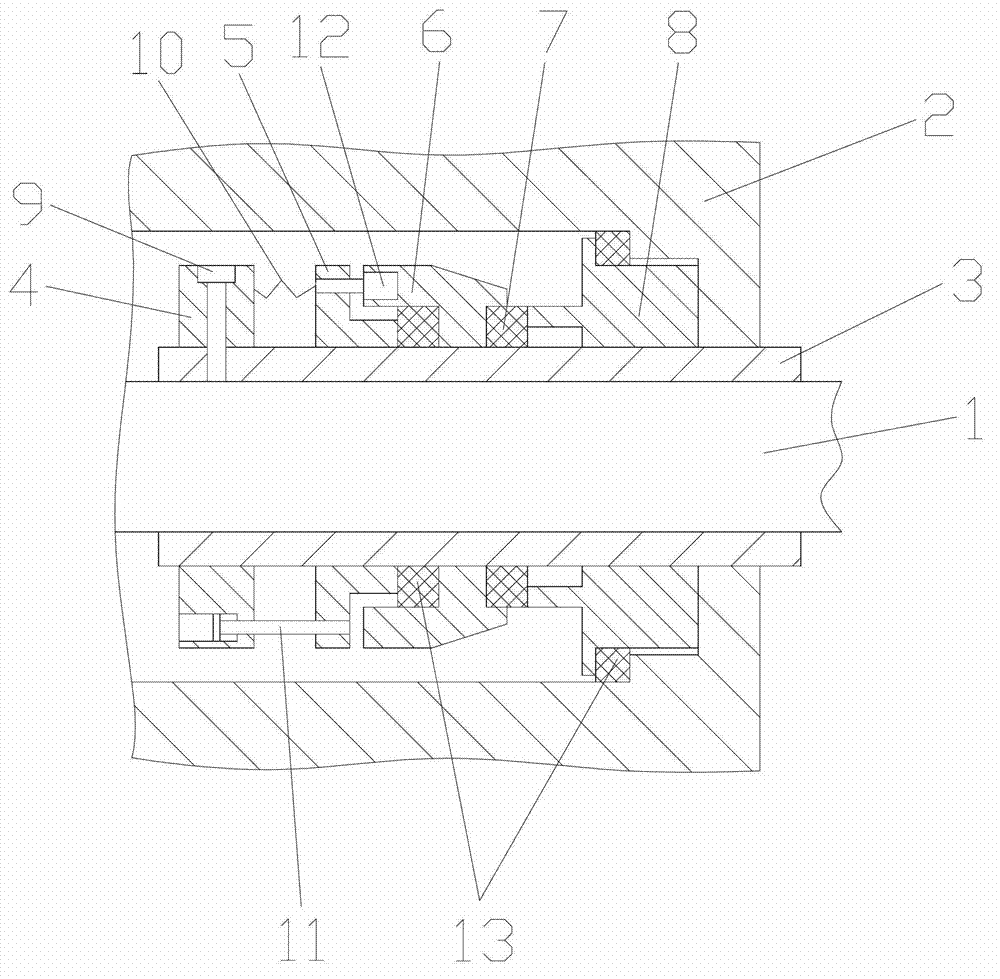
technical field [0001] The invention relates to a sealing device, in particular to a mechanical sealing device. Background technique [0002] With the development of society, a large number of mechanical rotating devices are used, and these devices are inevitably equipped with sealing devices. The sealing device can effectively reduce the leakage of the medium between the power input shaft and the casing, thereby reducing the energy consumption of the machine, increasing the unit input and output, and prolonging the service life of the machine. [0003] General seals (if attached figure 1 shown) includes power input shaft 1, housing 2, shaft sleeve 3, spring seat 4, push ring 5, compensation ring seat 6, moving ring 7, static ring 8, set screw 9, spring 10, transmission screw 11, The transmission pin 12 and the seal ring 13, the power input shaft 1 passes through the housing 2, and is arranged in the housing 2, the power input shaft 1 is covered with a shaft sleeve 3, and ...

Claims


Application Information

Patent Timeline
IPC IPC(8): F16J15/34
Inventor 叶晓峰
Owner SUZHOU DONGLI MACHINERY
Learn More