
Method using low-melting-point alloy for sealing micro heat pipe filling hole

A low-melting point, micro-heat pipe technology, applied in the process of producing decorative surface effects, micro-structure technology, indirect heat exchangers, etc., can solve micro-heat pipe failure, micro-heat pipe leakage, and unfavorable industrial production of micro-heat pipes and other issues to achieve the effect of expanding the application occasions

Active Publication Date: 2015-10-07
DALIAN UNIV OF TECH
View PDF6 Cites 8 Cited by
  • Summary
  • Abstract
  • Description
  • Claims
  • Application Information

AI Technical Summary

Problems solved by technology

The internal volume of the micro heat pipe ranges from tens of microliters to more than one hundred microliters. Due to the large reduction in the internal volume and the difference in materials, the traditional heat pipe potting method is no longer suitable for micro heat pipes.
Among them, the research on the sealing of micro heat pipes is still in the experimental stage. Sealant sealing can only temporarily solve the problem of working medium sealing. The main component of sealant is epoxy resin, and epoxy resin will absorb and dissolve gases in high vacuum The outgassing will be generated under the environment, causing problems such as the decrease of the vacuum degree in the tube or the air leakage of the micro heat pipe, which will cause the failure of the micro heat pipe; the micro heat pipe that uses copper capillary as the sealing interface has a large sealing junction after cold welding, and it will be damaged in the package. The structure is not conducive to the industrial production of micro heat pipes, which brings difficulties in product application

Method used


Image

  • Method using low-melting-point alloy for sealing micro heat pipe filling hole
  • Method using low-melting-point alloy for sealing micro heat pipe filling hole
  • Method using low-melting-point alloy for sealing micro heat pipe filling hole

Examples


Embodiment

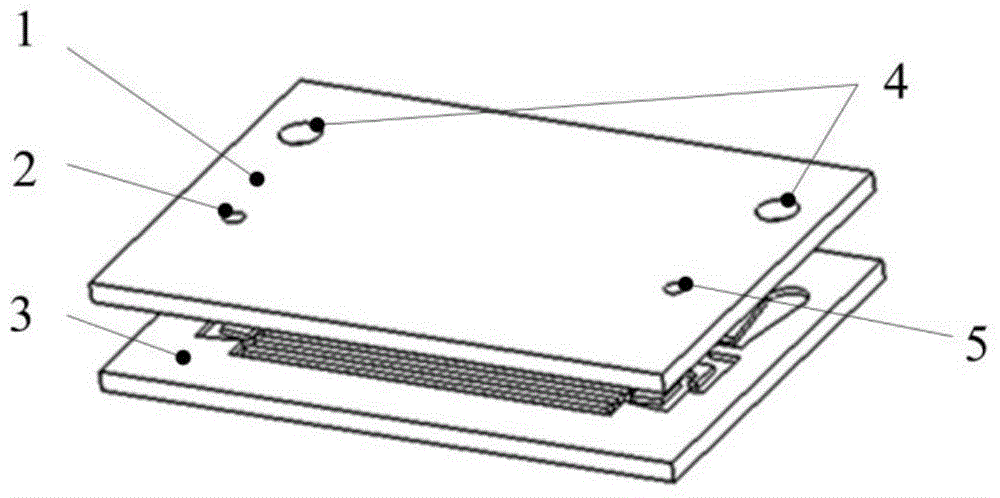
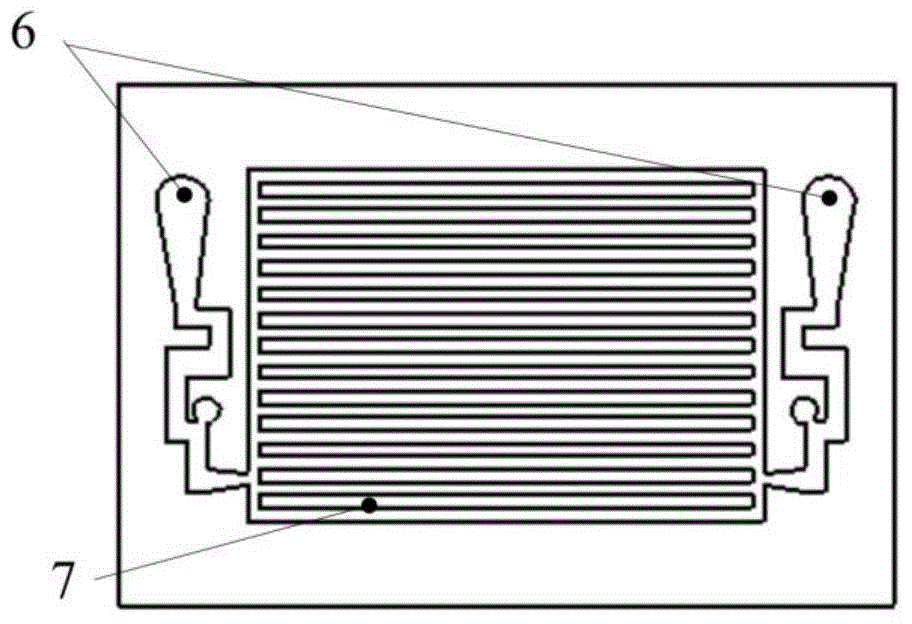
[0020] First, the glass cover plate and the silicon substrate are sealed together by anodic bonding, wherein the etching depth of the phase change channel and the perfusion channel on the silicon substrate is 150 μm to form a silicon-based micro heat pipe 13 .

[0021] In the second step, the silicon-based micro heat pipe is placed on the hot plate 14, and the temperature of the hot plate 14 is controlled to be 5° C. higher than the melting point of the low melting point alloy (the melting point of the low melting point alloy is 120° C.). A certain amount of liquid low melting point alloy is injected into the two pouring channels 6 through the low melting point alloy filling hole 4, and the silicon-based micro heat pipe is removed from the hot plate 14, and the low melting point alloy in the tube is cooled and solidified.

[0022] The third step is to connect the silicon-based micro heat pipe 13 to the vacuum filling circuit for vacuuming operation; after reaching the predeterm...


PUM

PropertyMeasurementUnit
depthaaaaaaaaaa

Abstract

The present invention discloses a method using a low-melting-point alloy for sealing a micro heat pipe filling hole, and the method is used for heat pipe packaging manufacturing and device heat dissipation, and belongs to the field of device packaging and heat dissipation. Before a working medium is filled, the low-melting-point alloy is preset in a silicon-based micro heat pipe, after completion of vacuumizing operation, a vacuumizing hole is sealed by low-melting-point alloy melting and solidification; and after the working medium filling proceeds, a working medium filling hole is sealed by low-melting-point alloy melting and solidification to complete the entire micro heat pipe filling operation. A micro heat pipe sealed with the method is free of a sealant, the method is suitable for solvents such as ethanol, acetone and the like as the filling working medium, the micro heat pipe has long-term sealing effect; and by use of the low-melting-point alloy for sealing, impact on micro heat pipe heat transfer properties due to material gas release can be reduced.

Description

technical field [0001] The invention belongs to the field of device packaging and heat dissipation, and relates to a packaging method for sealing a silicon-based micro heat pipe with a low-melting point alloy, which is applied to heat pipe packaging manufacturing and device heat dissipation. Background technique [0002] In recent years, heat pipe cooling technology has been experimentally researched, developed and applied in aerospace, energy, electronics and many other fields. Heat pipes have the advantages of large heat transfer capacity, good heat uniformity, and high thermal conductivity, and have been extensively studied by many scholars at home and abroad. The heat transfer performance of the heat pipe is affected by factors such as the perfusion volume of the working fluid, the perfusion vacuum, the working inclination angle, and the internal channel structure. Therefore, the packaging technology directly affects the quality of the micro heat pipe [TANG Y, et al. Col...

Claims


Application Information

Patent Timeline
Patent Type & Authority Applications(China)
IPC IPC(8): B81C1/00B81C3/00F28D15/02
Inventor 罗怡李聪明王晓东周传鹏于贝珂
Owner DALIAN UNIV OF TECH
Learn More