Quick centering device for engine pedestal test

An engine stand and centering device technology, which is applied in the direction of engine testing, measuring device, machine/structural component testing, etc., can solve problems such as difficulty in ensuring adjustment accuracy, complicated operation steps, and difficulty in finding interference problems.

Active Publication Date: 2013-01-30
BAODING WEIYI AUTOMOBILE CO LTD
View PDF5 Cites 20 Cited by
  • Summary
  • Abstract
  • Description
  • Claims
  • Application Information

AI Technical Summary

Problems solved by technology

The above-mentioned engine installation method has the following defects: 1. The coaxiality between the flywheel end of the engine crankshaft and the main shaft of the dynamometer is completely controlled by adjusting the position of the support legs, and the adjustment of the position of the support legs is achieved by beating with a heavy object such as a hammer. It is not easy to guarantee; 2. The cooling water pipeline, oil circulation pipeline, fuel pipeline and other facilities of the test

Method used


Image

  • Quick centering device for engine pedestal test
  • Quick centering device for engine pedestal test
  • Quick centering device for engine pedestal test

Examples


Embodiment Construction

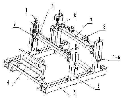
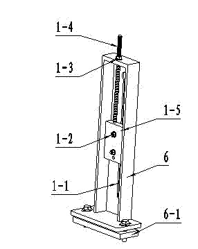
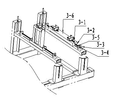
[0022] Referring to Fig. 1, the present invention comprises base 5, support frame 6, crossbeam 7 and quick plug panel 4, and described support frame 6 is made up of four groups of vertical supports, and they are all fitted with base 5, and each group of vertical supports An up and down adjustment mechanism 1 is provided, and a crossbeam 7 is arranged between the two sets of vertical supports. The up and down adjustment mechanism 1 is assembled with the crossbeam 7. The front and rear adjustment mechanisms 3 are fixed on the front and rear adjustment mechanisms 3 on the crossbeam 7. The engine support rubber seat 8 is installed, and the left and right fine adjustment mechanisms 2 are also provided at the front and rear ends of the beam 7 .

[0023] See Figure 1, Figure 5 , the base 5 of the present invention is composed of a base beam 5-4 and a base longitudinal beam 5-5, the base beam 5-4 includes two parts arranged left and right, wherein the left base beam is provided with ...


PUM


Abstract

The invention provides a quick centering device for an engine pedestal test, which is used for quickly centering the crankshaft flywheel end of an engine to a main shaft of a dynamometer. The quick centering device comprises a base, a supporting frame, a beam and a quick plug panel, wherein the supporting frame comprises four groups of vertical supports which are all assembled to the base; an up-down adjusting mechanism is arranged on the vertical support in each group; beams are arranged between each two opposite groups of vertical supports; the up-down adjusting mechanisms are assembled to the beams; a front-back adjusting mechanism is arranged on each beam; rubber engine support seats are fixedly arranged on the front-back adjusting mechanisms; and a fine left-right adjusting mechanism is also arranged at the front and rear ends of each beam. The quick centering device allows the centering adjustment on the crankshaft flywheel end of the engine and the main shaft of the dynamometer in the engine pedestal test to be easy, is high in adjustment precision, eliminates the shortcomings of the conventional centering way of beating through a heavy object such as an iron hammer, avoids the waste of a pedestal resource when the centering operation is performed in a laboratory, and can realize quick butt-joint of water channels, oil channels and sensor lines and improve the working efficiency.

Description

technical field [0001] The invention relates to an engine bench test auxiliary device, in particular to a quick centering device suitable for the main shaft of an engine bench test dynamometer and a flywheel end of a crankshaft of an engine, and belongs to the technical field of engine testing. Background technique [0002] Before the bench test of the engine, it is necessary to precisely adjust the coaxiality and flatness of the crankshaft flywheel end of the engine and the main shaft of the dynamometer. The adjustment accuracy is not only directly related to the reliability of the test results, but also affects the engine performance and The service life of the dynamometer. In addition, in the case of limited resources of the test bench, the length of the experiment preparation time determines the utilization rate of the bench resources. [0003] According to the requirements of the engine bench test, the coaxiality error between the flywheel end of the engine crankshaft a...

Claims


Application Information

Patent Timeline
IPC IPC(8): G01M15/02
Inventor 张卫罗松灿刘克明时栓柱
Owner BAODING WEIYI AUTOMOBILE CO LTD
Why Eureka
Try Eureka