Optical touch device and optical sensor thereof

An optical touch and light sensor technology, applied in the direction of instrument, electrical digital data processing, data processing input/output process, etc., can solve the problem of complex driving circuit, and achieve the effect of simple driving circuit

Inactive Publication Date: 2013-01-30
PIXART IMAGING INC
View PDF3 Cites 1 Cited by
  • Summary
  • Abstract
  • Description
  • Claims
  • Application Information

AI Technical Summary

Problems solved by technology

[0006] In the existing optical touch device 100, since the light sources 120a and 120b must have two light emitting states, the driving circuits of the light sources 120a and 120b are relatively complicated.

Method used


Image

  • Optical touch device and optical sensor thereof
  • Optical touch device and optical sensor thereof
  • Optical touch device and optical sensor thereof

Examples


Embodiment Construction

[0040] In order to further explain the technical means and effects of the present invention to achieve the intended purpose of the invention, the specific implementation, structure, The features and their functions are detailed as follows:

[0041] The aforementioned and other technical contents, features and effects of the present invention will be clearly presented in the following detailed description of preferred embodiments with reference to the drawings. Through the description of specific implementation methods, the technical means and effects of the present invention to achieve the intended purpose can be understood more deeply and specifically, but the attached drawings are only for reference and description, and are not used to explain the present invention limit.

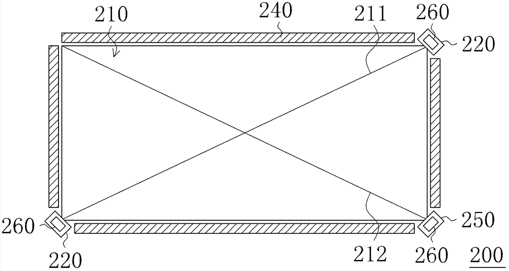
[0042] figure 2 is a schematic diagram of an optical touch device according to an embodiment of the present invention. Please refer to figure 2, the optical touch device 200 of this embodiment has a...


PUM


Abstract

The invention relates to an optical sensor. The optical sensor comprises a shell with an incident side, a reflective layer and a photo-sensitive element. The reflective layer covers part of the incident side so that an incident area uncovered by the reflective layer and a reflective area beside the incident area are formed on the incident side. The photo-sensitive element is arranged inside the shell, and a photo-sensitive surface of the photo-sensitive element faces to the incident area. In addition, the invention provides an optical touch device comprising the optical sensors. The optical touch device comprises two optical sensors which are disposed on two opposing sides of a sensing area of the optical touch device. The defect that dark fields easily occur to setting positions of the optical sensors on the optical touch device can be overcome.

Description

technical field [0001] The present invention relates to a touch device, and in particular to an optical touch device and an optical sensor thereof. Background technique [0002] Touch devices have the advantage of easy operation, so in recent years, touch devices have been widely used in various electronic products, such as mobile phones, personal digital assistants (personal digital assistant, PDA), digital cameras, music players, computers, Satellite navigation devices, touch screens, etc. Common touch devices currently include resistive touch devices, capacitive touch devices, and optical touch devices, among which the optical touch device has the advantage of lower cost. [0003] figure 1 It is a schematic diagram of an existing optical touch device. Please refer to figure 1 , the existing optical touch device 100 has a sensing area 101, and the optical touch device 100 includes three light sensors 110a, 110b, 110c, three light sources 120a, 120b, 120c and four refle...

Claims


Application Information

Patent Timeline
Patent Type & Authority Applications(China)
IPC IPC(8): G06F3/042
Inventor 陈晖暄
Owner PIXART IMAGING INC
Why Eureka
Try Eureka